Rob's 3D CAD workbench
Moderators: 52D, Tom F, Rlangham, Atlantic 3279, Blink Bonny, Saint Johnstoun, richard
-
Robpulham

- LNER A4 4-6-2 'Streak'
- Posts: 1719
- Joined: Thu Mar 27, 2008 9:54 pm
- Location: Lower Wensleydale
- Contact:
Re: Rob's 3D CAD workbench
A bit more dabbling has created a round tank filler for a J52 (there was also an oval version). This is in 4mm for a friend but I will no doubt scale it up to upgrade the one n my own kit.
-
Robpulham
- LNER A4 4-6-2 'Streak'
- Posts: 1719
- Joined: Thu Mar 27, 2008 9:54 pm
- Location: Lower Wensleydale
- Contact:
Re: Rob's 3D CAD workbench
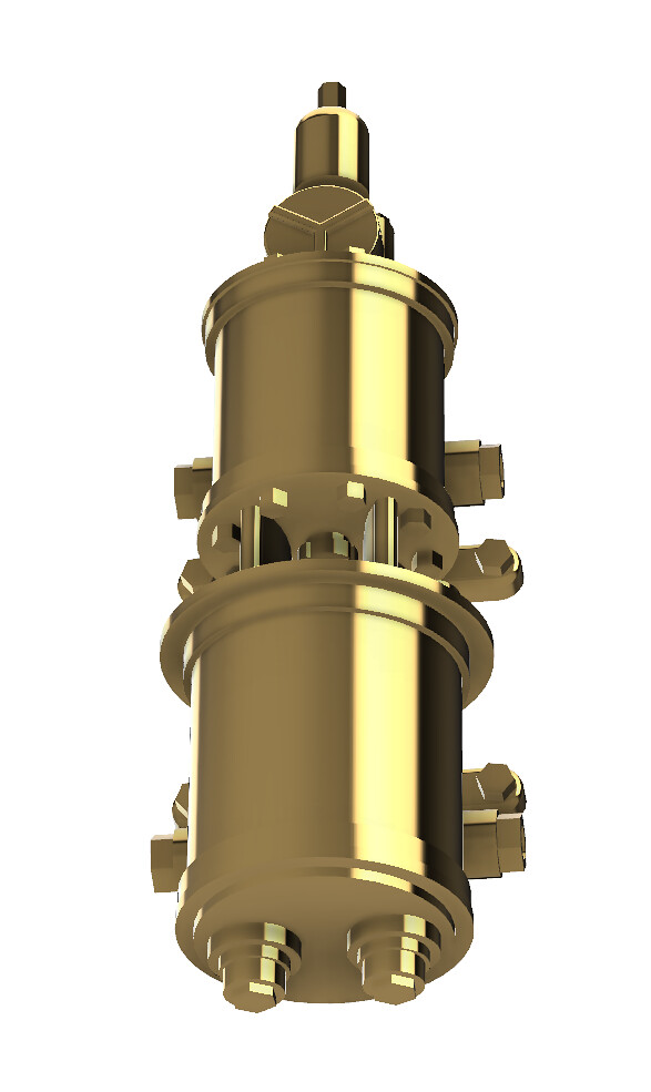
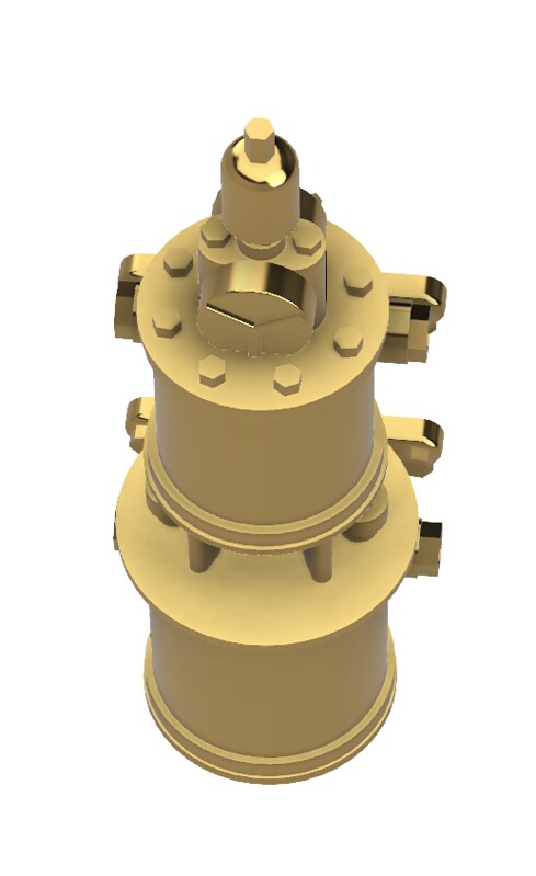
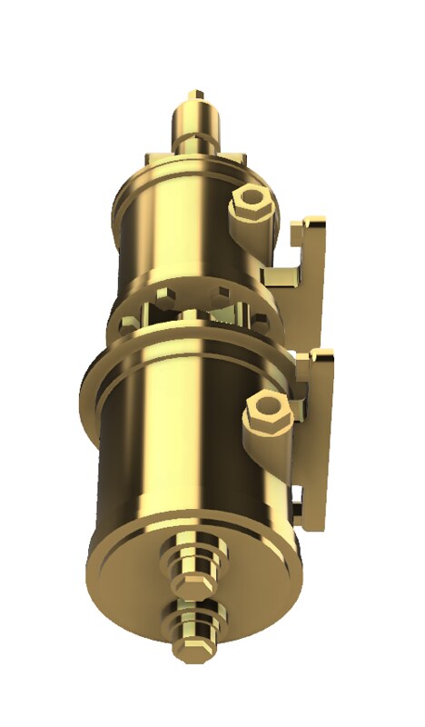
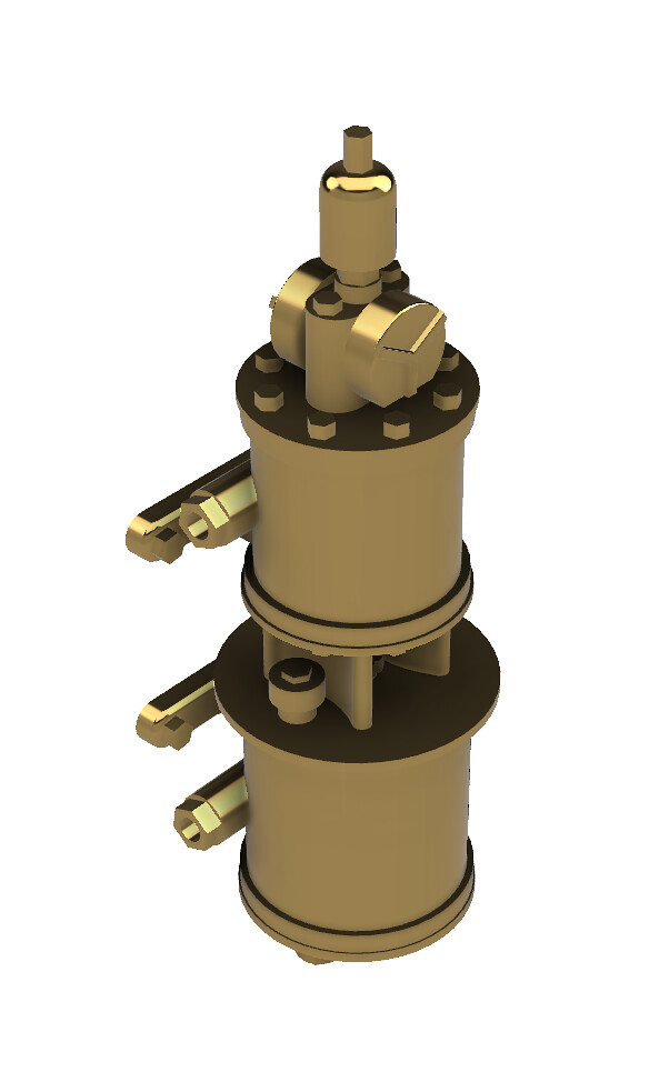
Hot of the 3D workbench is this Westinghouse Pump, those of you going to Thirsk may get to see the 7mm version in the flesh depending on when my mate arrives with the prints.

-
Robpulham
- LNER A4 4-6-2 'Streak'
- Posts: 1719
- Joined: Thu Mar 27, 2008 9:54 pm
- Location: Lower Wensleydale
- Contact:
Re: Rob's 3D CAD workbench
A friend kindly printed the Westinghouse pump and brought some along to Thirsk show yesterday.
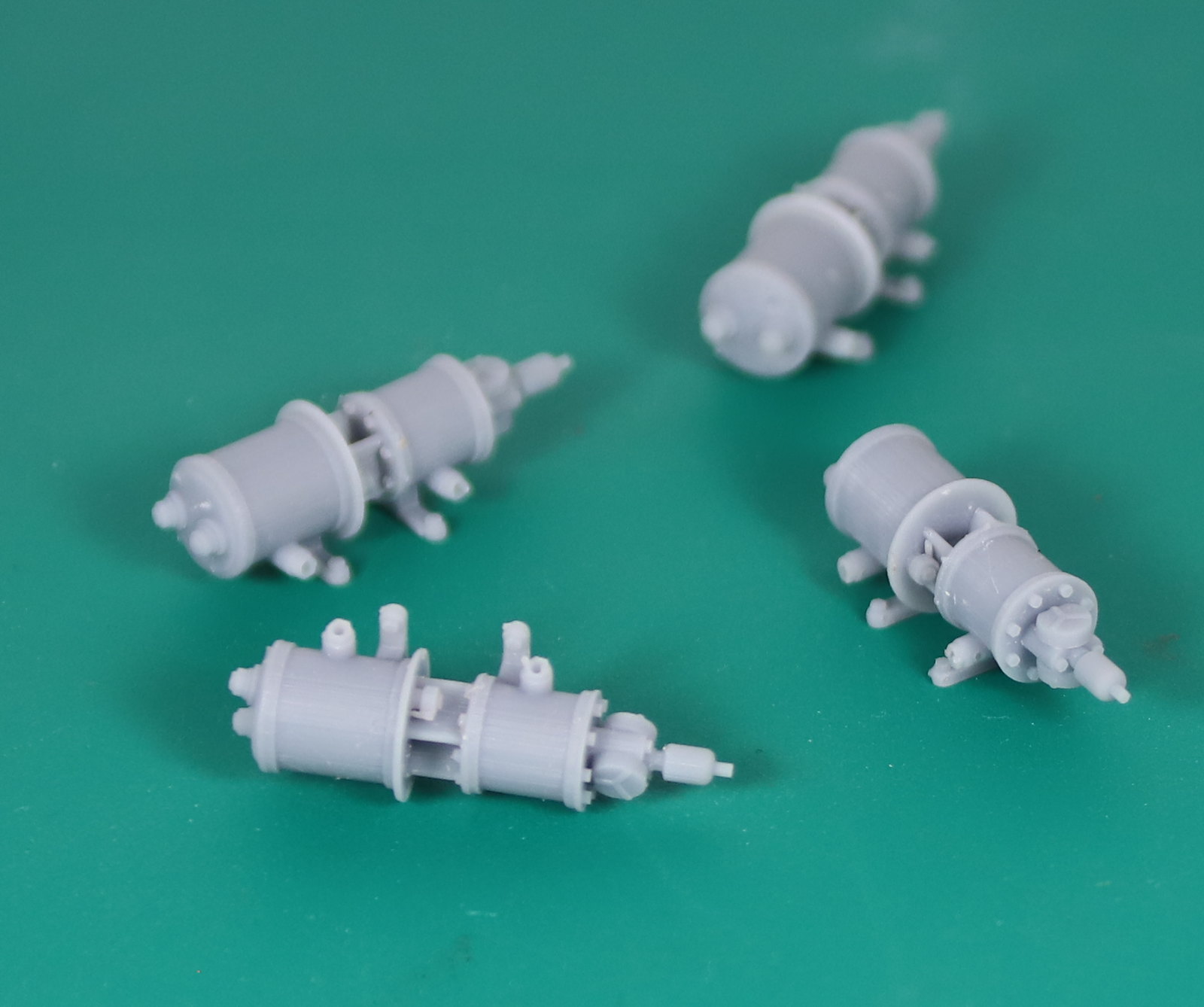
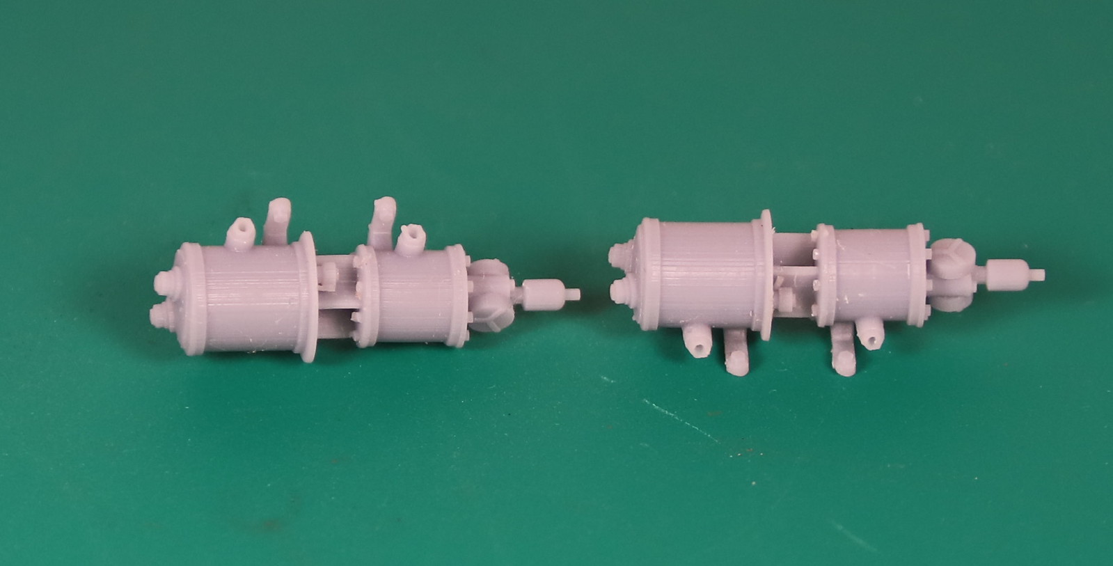
I am most impressed with the print quality
I am most impressed with the print quality

-
Dave

- LNER A4 4-6-2 'Streak'
- Posts: 1700
- Joined: Sat Nov 13, 2010 9:33 pm
- Location: Centre of the known universe York
Re: Rob's 3D CAD workbench
Good to meet up at Thirsk Rob.
I was very impressed with the pumps and the LNER bits you had, brilliant work.
I was very impressed with the pumps and the LNER bits you had, brilliant work.
-
Robpulham
- LNER A4 4-6-2 'Streak'
- Posts: 1719
- Joined: Thu Mar 27, 2008 9:54 pm
- Location: Lower Wensleydale
- Contact:
Re: Rob's 3D CAD workbench
Thanks Dave, it was good to meet up again with you too.
-
Robpulham
- LNER A4 4-6-2 'Streak'
- Posts: 1719
- Joined: Thu Mar 27, 2008 9:54 pm
- Location: Lower Wensleydale
- Contact:
Re: Rob's 3D CAD workbench
Over on one of the other forums, I was asked for help in the form of how to go about drawing up an NSR lamp post
On the basis of the drawing I had a few ideas of who I might go about it and once I had it cracked I was asked for an explanation of how I had gone about it. I thought I would share it wider as it might help someone at some point. You will have to excuse some of the wording that relates to answering the initial question. I haven't the time at the moment to go through and re write it.
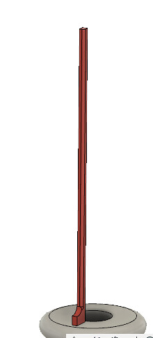
This was the drawing attached to the request for help.
First, I downloaded Andy's drawing and imported it into Fusion on the front plane. Then as I said previously but repeated here for completeness. Because the drawing had no dimensions, I best guessed that the main part of the post would be around 10 feet tall - I was way out as it's only around 6ft when taken right to the ground!
However, using the 10ft as the basis, I created myself a User Parameter of 1ft/7mm which allowed me to quickly scale the drawing to 7mm to the foot.
Next, I drew a profile of the lamp base and revolved it.

Then I worked out the middle of the column height wise and created an offset plane.

Then, I created a sketch on that offset plane and drew the shape for my cut out

I only drew one of the shapes then used the 'create circular pattern' tool to create the other five. As it turned out, initially I had the outer circle slightly under the column sized so when I extruded as a cut it was actually inside the body.
I then, extruded using the symmetrical function and cut command so I was going both up and down to get the cut outs in place all around the column.

On the basis of the drawing I had a few ideas of who I might go about it and once I had it cracked I was asked for an explanation of how I had gone about it. I thought I would share it wider as it might help someone at some point. You will have to excuse some of the wording that relates to answering the initial question. I haven't the time at the moment to go through and re write it.
This was the drawing attached to the request for help.
However, using the 10ft as the basis, I created myself a User Parameter of 1ft/7mm which allowed me to quickly scale the drawing to 7mm to the foot.
Next, I drew a profile of the lamp base and revolved it.
Then I worked out the middle of the column height wise and created an offset plane.
Then, I created a sketch on that offset plane and drew the shape for my cut out
I only drew one of the shapes then used the 'create circular pattern' tool to create the other five. As it turned out, initially I had the outer circle slightly under the column sized so when I extruded as a cut it was actually inside the body.
I then, extruded using the symmetrical function and cut command so I was going both up and down to get the cut outs in place all around the column.
-
Robpulham
- LNER A4 4-6-2 'Streak'
- Posts: 1719
- Joined: Thu Mar 27, 2008 9:54 pm
- Location: Lower Wensleydale
- Contact:
Re: Rob's 3D CAD workbench
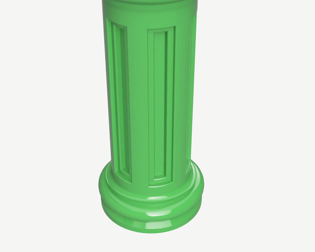
Next, I drew a couple of upright lines on the first sketch to determine the width of the base of the fluted section. Which was 8mm on my overscale drawing. Then I created another offset plane this time at the top of the column/base of the fluted section.

Then, I created a sketch on that plane and drew a circle 8mm in diameter, on the edge of that circle I drew another circle 0.6mm in diameter. Using these as a best guess for the size of the flute. I then used the circular pattern tool to create circle all around the inner circle. this ended up being 42.

Then on the first sketch I drew the profile of the flute.

I extruded this again symmetrically 0.3mm either way, to give me the 0.6mm thickness that I had determined (best guess!!!) was the flute size. Then I filleted the front edges to give me the round flute

Lastly, I used the circular pattern tool again to create the circle of 42.


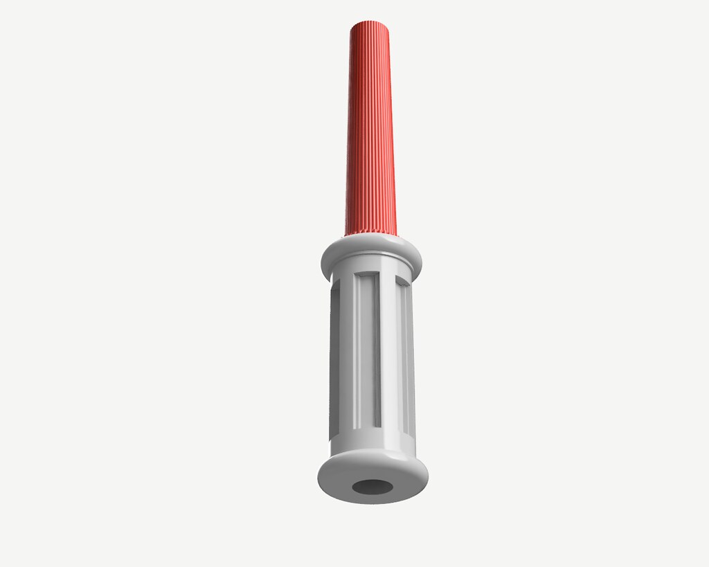
I even managed to get the render tool to work this morning last night I think that my machine was doing an update in the background and it was running like a dog.
Then, I created a sketch on that plane and drew a circle 8mm in diameter, on the edge of that circle I drew another circle 0.6mm in diameter. Using these as a best guess for the size of the flute. I then used the circular pattern tool to create circle all around the inner circle. this ended up being 42.
Then on the first sketch I drew the profile of the flute.
I extruded this again symmetrically 0.3mm either way, to give me the 0.6mm thickness that I had determined (best guess!!!) was the flute size. Then I filleted the front edges to give me the round flute
Lastly, I used the circular pattern tool again to create the circle of 42.
I even managed to get the render tool to work this morning last night I think that my machine was doing an update in the background and it was running like a dog.
-
Robpulham
- LNER A4 4-6-2 'Streak'
- Posts: 1719
- Joined: Thu Mar 27, 2008 9:54 pm
- Location: Lower Wensleydale
- Contact:
Re: Rob's 3D CAD workbench
In conclusion, I got an annotated copy of the drawing so I was able to scale it to 7mm and do the complete pole.


-
Robpulham
- LNER A4 4-6-2 'Streak'
- Posts: 1719
- Joined: Thu Mar 27, 2008 9:54 pm
- Location: Lower Wensleydale
- Contact:
Re: Rob's 3D CAD workbench
because it's meant to represent something that has been cast I went round and softened some of the edges using the fillet tool


-
Robpulham
- LNER A4 4-6-2 'Streak'
- Posts: 1719
- Joined: Thu Mar 27, 2008 9:54 pm
- Location: Lower Wensleydale
- Contact:
Re: Rob's 3D CAD workbench
It was pointed out over on Western Thunder that the inset in the base should have the profile all the way around which I agree it should but I couldn't work out how to do it. As always the minute that I started to reply to the gent who raised it I thought of how I might achieve it.
-
Robpulham
- LNER A4 4-6-2 'Streak'
- Posts: 1719
- Joined: Thu Mar 27, 2008 9:54 pm
- Location: Lower Wensleydale
- Contact:
Re: Rob's 3D CAD workbench
I haven't posted much since finishing the J6 as I am still working on a Princess Royal so not really relevant to the LNER
However these are, albeit not so much my 3D workbench most of yesterday was spent lettering some 3D printed wagons that I have painted for a friend who does my 3D printing for me.
NER K1 Cattle Wagon


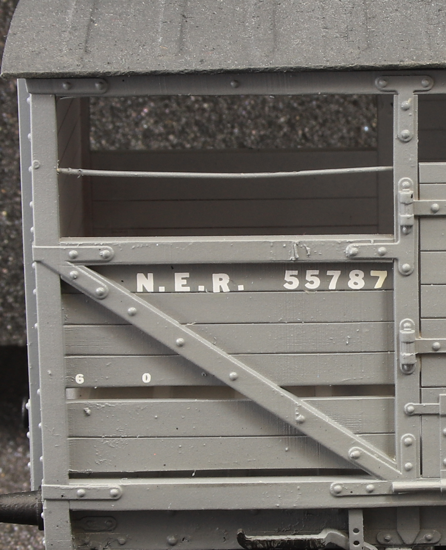
NER P6 Hopper Wagon


I have examples of each of these to build for myself at some point too.
However these are, albeit not so much my 3D workbench most of yesterday was spent lettering some 3D printed wagons that I have painted for a friend who does my 3D printing for me.
NER K1 Cattle Wagon
NER P6 Hopper Wagon
I have examples of each of these to build for myself at some point too.
-
Robpulham
- LNER A4 4-6-2 'Streak'
- Posts: 1719
- Joined: Thu Mar 27, 2008 9:54 pm
- Location: Lower Wensleydale
- Contact:
Re: Rob's 3D CAD workbench
I have been a bit quiet on this forum of late and that's mainly because my major project has been an LMS Princess Royal loco which I didn't think would really fit well on an LNER focussed forum.
That said much of January has been spent redesigning a Firebox in Fusion 360 for 3D printing and I think that I am there with it now (subject to what I hope is a final test print).
This is the 7th iteration of the design but I have only had a couple of them printed so far. The good news, for me at least is that the lower firebox pieces, have only needed to be printed twice. They are fine so the last test print will only be the upper firebox.