Page 29 of 29
Re: Copenhagen Fields & TFW’s workshop
Posted: Fri Apr 26, 2024 10:40 am
by Mickey
Tim Watson wrote: ↑Thu Apr 25, 2024 7:26 pm
[/URL]
Maybe we should just put a steam generator in the tunnels, so they’re hidden, a bit…
Well
Gasworks tunnel was called
The tunnel that never stops smoking!.
Re: Copenhagen Fields & TFW’s workshop
Posted: Sun Apr 28, 2024 6:18 pm
by Horsetan
Tim Watson wrote: ↑Thu Apr 25, 2024 7:26 pm...
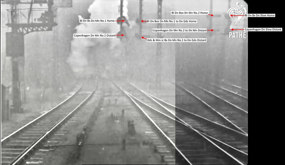
There aren’t any decent close up photos of it, but these are the arms that will be modelled. At least two of them should probably work sometime, as they signal a conflicting route, but we’ll see.
Maybe we should just put a steam generator in the tunnels, so they’re hidden, a bit…
In this context, what do "Bl" and "Bx" stand for?
Re: Copenhagen Fields & TFW’s workshop
Posted: Sun Apr 28, 2024 7:48 pm
by Tim Watson
Belle Isle Down Box.
Tim
Re: Copenhagen Fields & TFW’s workshop
Posted: Sun Apr 28, 2024 10:07 pm
by Tim Watson
Some more progress on the signal gantry at Gasworks Tunnel.

The dolls were filed up very quickly from some 2mm square brass. I use very sharp, coarse, Vallorbe files to shift metal and then dress with finer grades.

The bridge is only partly planked, with over half open at the top. This was not catered for in the etch and so it required the herringbone bracing to be made. This was bent up from brass wire.


After bending, the wire was flattened in a vice and soldered in place one node at a time. It has strengthened the structure rather well, as have the lower footboards for the signal dolls.

Should add a bit of interest in the ‘trough’.
Tim
Re: Copenhagen Fields & TFW’s workshop
Posted: Mon Apr 29, 2024 8:59 pm
by Jim de Griz
Tim Watson wrote: ↑Sun Apr 28, 2024 10:07 pm
After bending, the wire was
flattened in a vice and soldered in place one node at a time. It has strengthened the structure rather well, as have the lower footboards for the signal dolls.
As always, fascinating to see the process you use to build these items, and I cannot believe I didn't think of that!
Jim de Griz
Re: Copenhagen Fields & TFW’s workshop
Posted: Tue Apr 30, 2024 9:59 pm
by Horsetan
Tim Watson wrote: ↑Sun Apr 28, 2024 7:48 pm
Belle Isle Down Box.
Thanks
Re: Copenhagen Fields & TFW’s workshop
Posted: Tue May 07, 2024 10:34 pm
by Tim Watson
After a bit of fiddling there is now a working somersault signal on the Belle Isle Down signal bridge on CF. There will be another arm working (these two signal a conflicting route) and the other 6-8 can be in fixed positions. I’ll try and take construction photos when the next one is being made.

The signal arm was chemically blackened to prevent it being soldered solid.

The video shows it simply being pulled on its connecting rodding. There will need to be some cranks and linkages across the bridge to activate it.
https://youtube.com/shorts/VnEL8bWzMaU? ... 0BXnNldx1-
Tim
Re: Copenhagen Fields & TFW’s workshop
Posted: Wed May 08, 2024 12:31 am
by rob
I've done somersaults in 4mm,single post and thought I was a very clever boy....then the A2...that westinghouse pump......I need to lie down in a darkened room!!.. fascinating work!
Re: Copenhagen Fields & TFW’s workshop
Posted: Sat May 11, 2024 12:35 am
by Tim Watson
As mentioned previously, I have taken some photos of the fabrication of the second somersault signal. The main components come from MSE (Wizard Models). The etch doesn’t quite manage the holes for the operating linkage so these were drilled out 0.2mm for the linkage and 0.3mm for the pivot.

The signal arm bracket requires a bit of work to help locate it on the doll. Working on the principle that it easier to drill a long 0.5mm hole through the doll rather than 0.3mm, the bracket was bushed with a length of Albion Alloys brass tube, OD 0.5mm, ID 0.3mm. This then acts as the pivot for the spectacle and back blind. The far end of the bracket also needed building out with a washer. These components were located in a vermiculite block using pins and soldered together.

The pivot bush makes it easy to locate the bracket on the doll.

Once in place, the front face of the pivot on the bracket was filed flush, as the spectacle has to work behind the signal arm.

The spectacle was soldered to some 0.3mm brass rod and filed flush. It was then linked up with a length of thin phosphor bronze wire through the 0.2mm diameter hole in the actuator arm.

The PB linkage was bent forward in the position of the application point on the signal arm.

The three components were then chemically blacked to prevent soldering (but scraped off where the collars / back blind needed to be soldered on.

Once on the bracket the pivot pins were retained with a collar and the back blind, which was also used to connect the drive rod.


This arm doesn’t quite pivot as vertically as the other one: the linkage length and pivot relationship is critical, but it is within the normal range. I am jolly glad that I don’t have any more to make as working arms on this signal bridge as my patience and eyes are pretty well exhausted.
Tim
Re: Copenhagen Fields & TFW’s workshop
Posted: Mon May 13, 2024 8:53 am
by Atlantic 3279
Having followed the same procedures working from the exact equivalent etch but in easier 4mm scale a couple of months ago, mainly to make single arm, single post signals (save for one example with co-acting high and low arms), I can imagine the even greater degree of difficulty attached to keeping the tolerances tight enough to avoid loss of movement, while maintaining free movement, plus arranging the extra rods and cranks for a signal bridge, all in only half of the size!