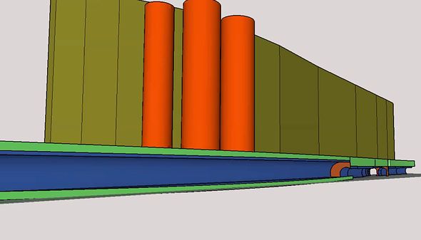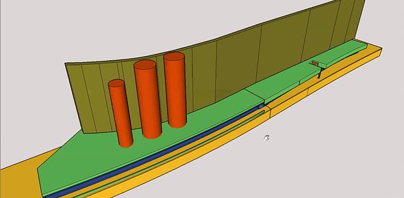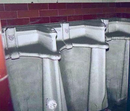
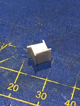
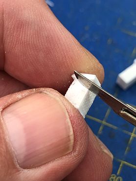
The stacks were made from solid Evergreen strip, clad in our brick styrene as shown: this building technique does not require great accuracy in measuring.
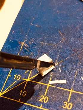
The excess vertical strips were cut off with a scalpel, followed by dressing the corners with a file.
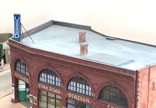
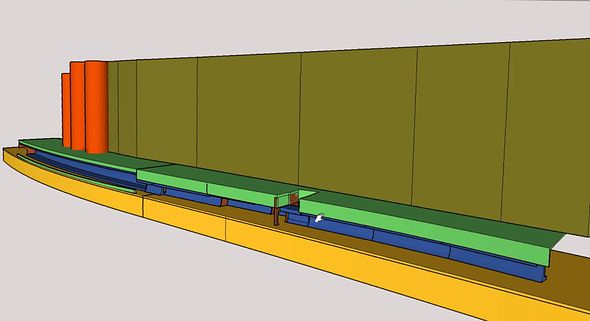
The bottom of the stack was given a 1mm thick styrene layer to represent the flashing and the top decorative courses also built out with layers. The edges of the brickwork were notched with the scalpel blade to soften them. Plastikard buildings often look too ‘sharp’ and ‘edgy’. For a more poorly maintained building a slotting file will give a more pronounced mortar course. The chimney castings complete with flaunchings will be epoxied on at a later stage.
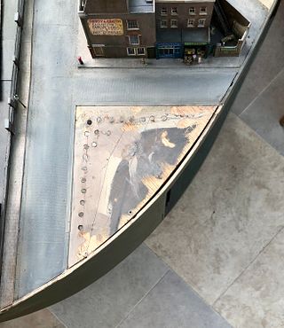
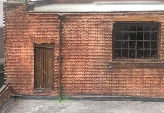
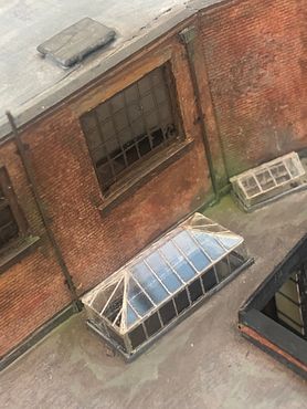
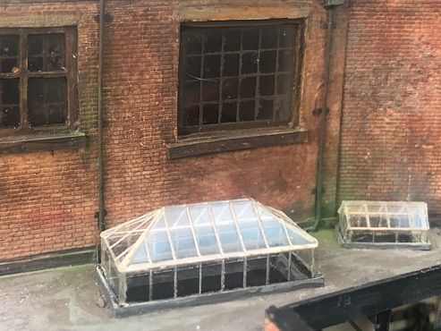
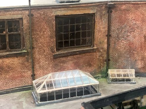
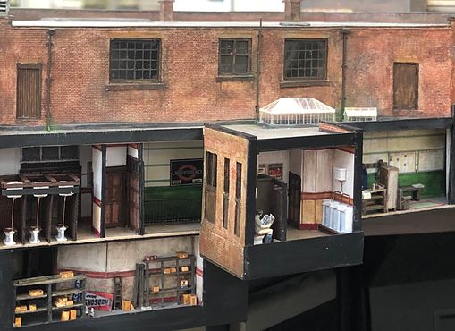
The roof was initially given a light grey wash applied in a random direction, then a darker grey with the brush in one direction only, followed by the light colour again at 90 degrees, building up texture and depth of colour along the way. Finally, a wash of a brown-grey was run along the gutters, corners and crevices. When the paint has hardened overnight, I will paint in some dried up puddles and other features and add some further weathering using powders, especially around the vent.
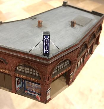
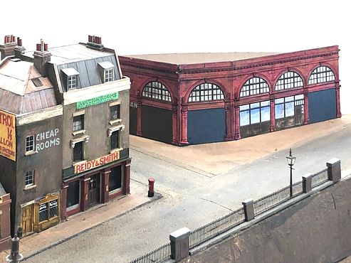
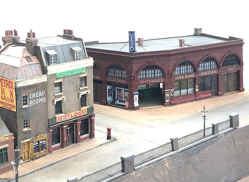
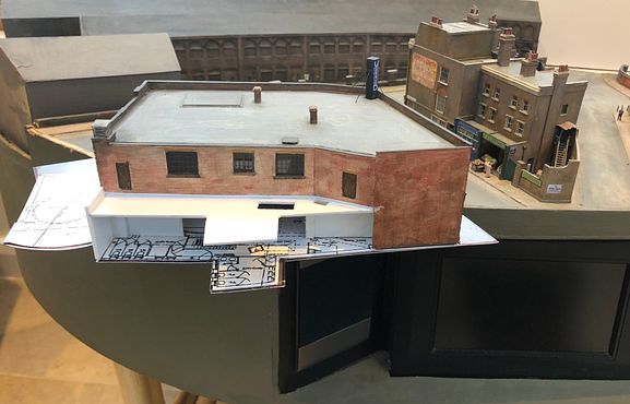
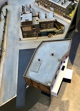
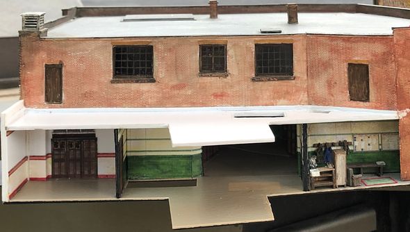
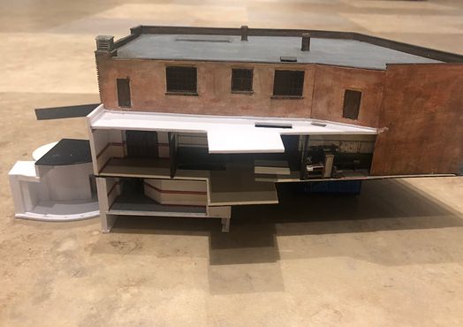
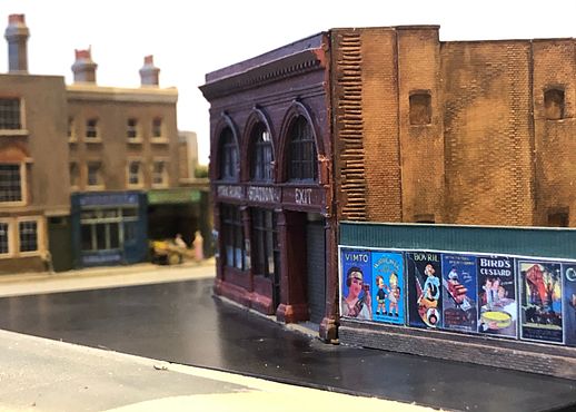
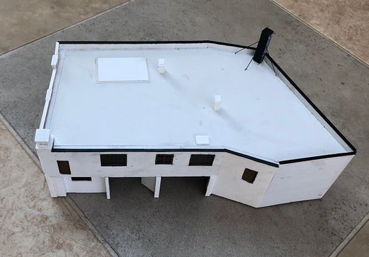
The building is looking very solid sitting on the layout - I believe a worthwhile improvement on the original concept (I’ll take some comparison photos soon).
Tim