Copenhagen Fields & TFW’s workshop

This forum is for the discussion of railway modelling of the LNER and its constituent companies.

Moderators: 52D, Tom F, Rlangham, Atlantic 3279, Blink Bonny, Saint Johnstoun, richard

Tim Watson
GER D14 4-4-0 'Claud Hamilton'
Posts: 312
Joined: Mon Oct 24, 2016 11:37 am

Re: Copenhagen Fields & TFW’s workshop

Post by Tim Watson »

York Road spiral stairs are now complete, after a weeks work: the illuminated steps will help to draw attention to the lift and give a raisin d’être for the funny shape on the southern side of the tube station. 
Image
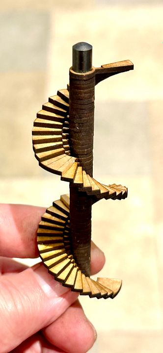
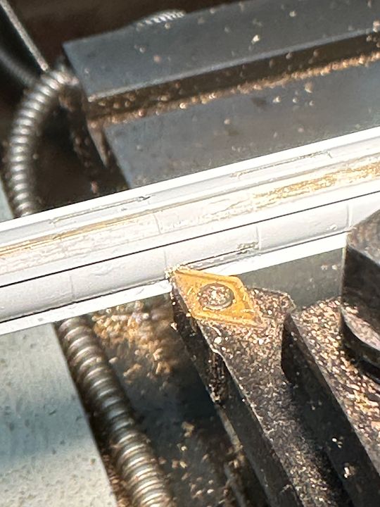
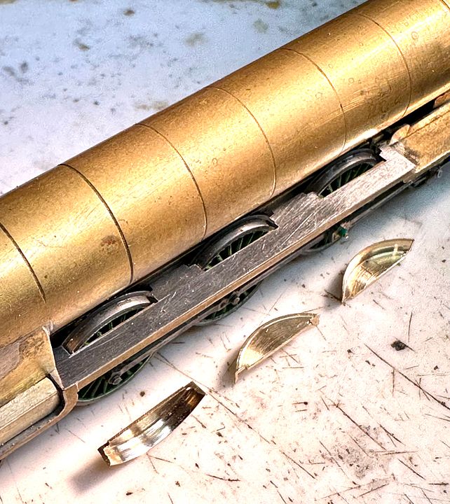
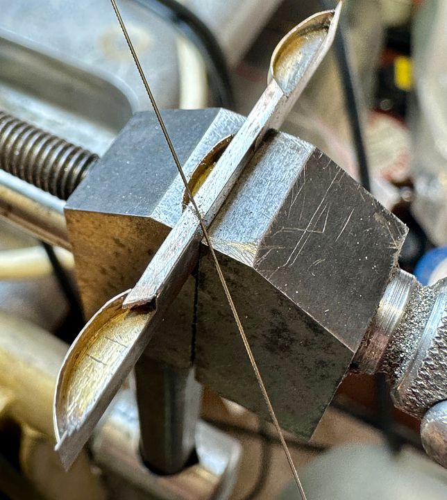
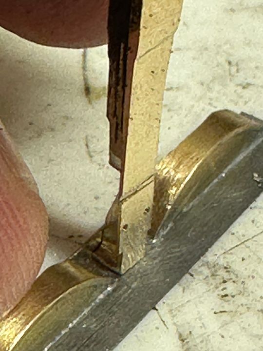
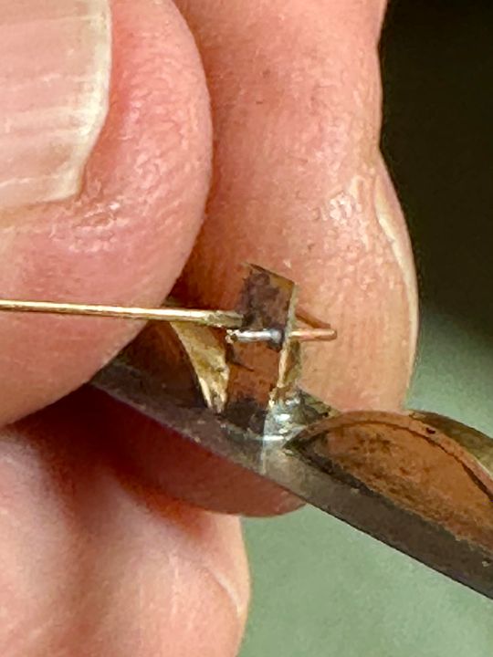
The construction was aided by John Jesson producing laser cut step sections using the MRC laser-cutting facility; rather like a castle stairway (the top step shows the profile). 
Image
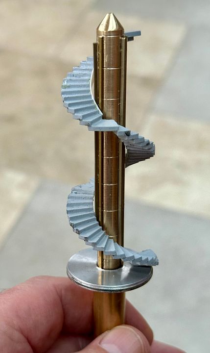
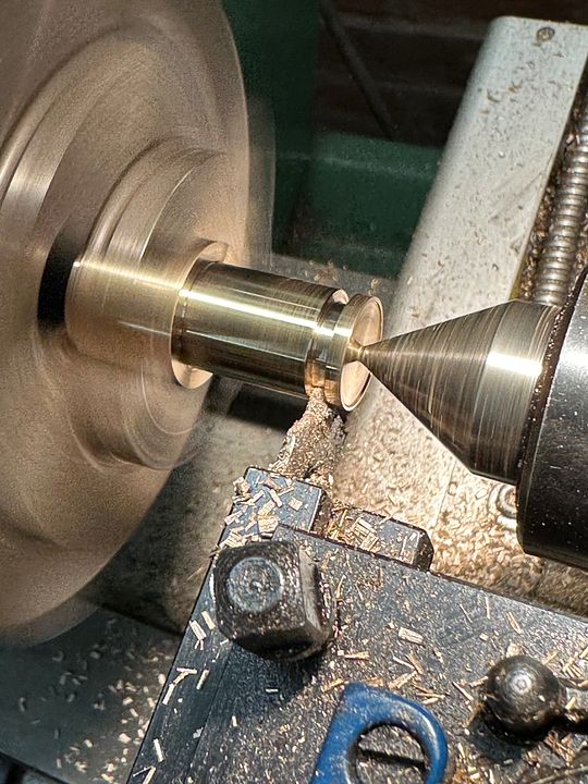
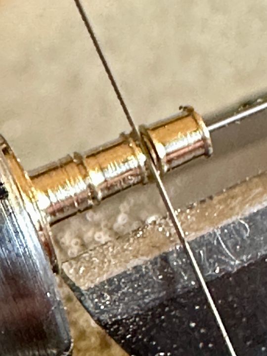
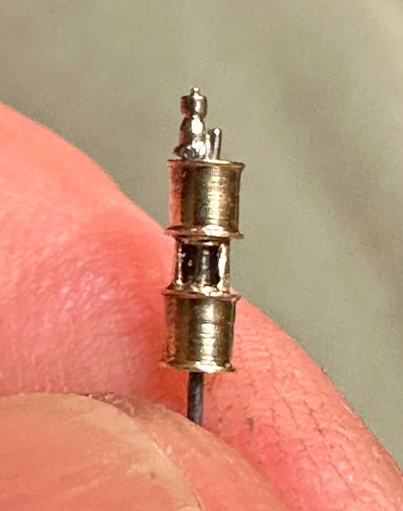
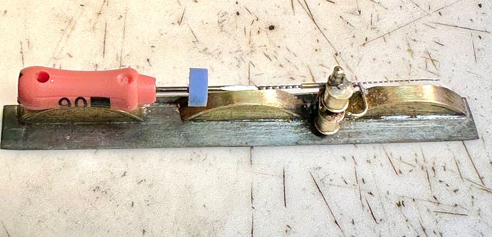
Once glued together, the centre section was cut away, the steps trimmed with a high speed tungsten carbide trimmer and a new brass ventilation shaft turned up to the correct diameter, complete with plate work jounts scribed into place. The aluminium collar helps to centralise and support the stairs towards the bottom. The reason for the polished conical tip will become apparent later (it’s not an ICBM).  
Image
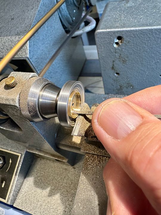
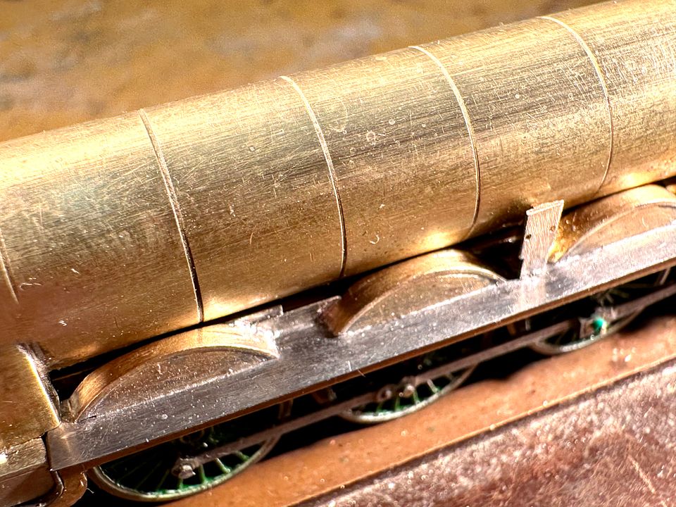
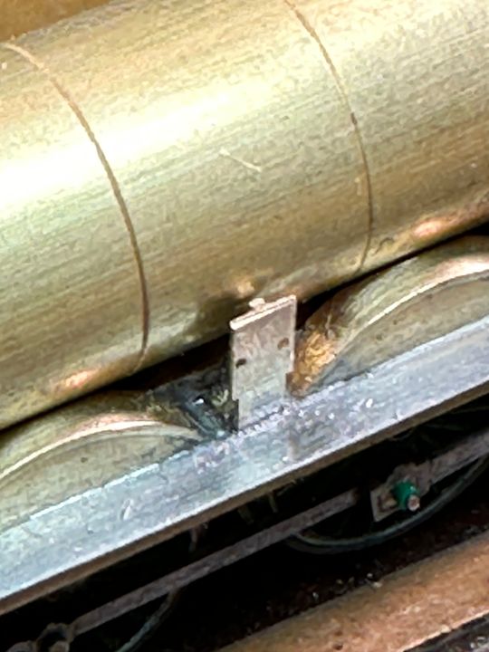
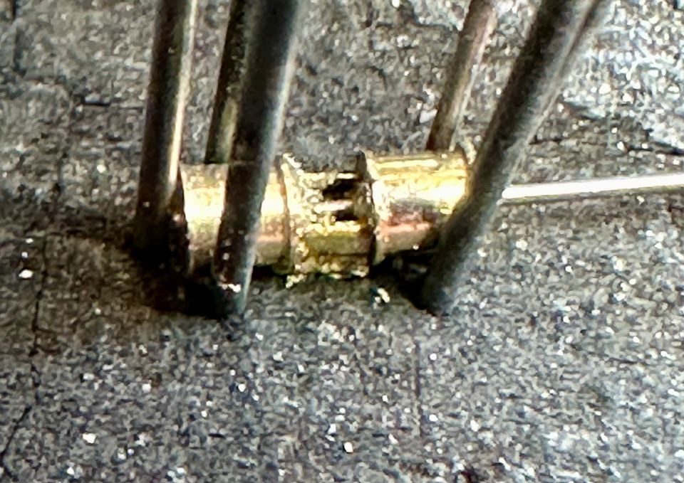
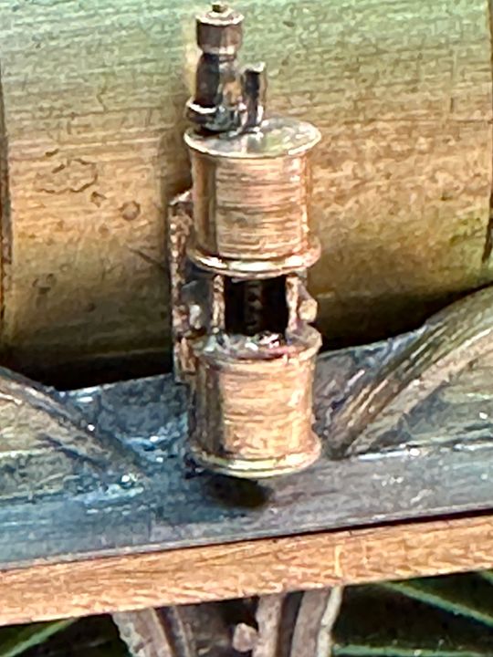
The copper pipe of the stair shaft had a window cut into it using diamond discs and the position of the stairs was then determined. Image
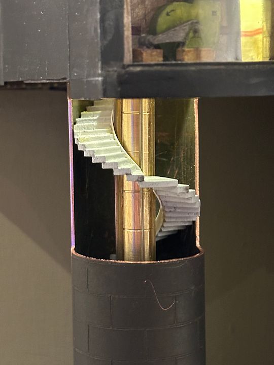
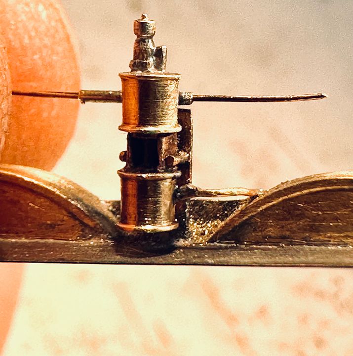
There are a number of conduits surrounding the ventilation shaft and these were represented by brass square section and strip. The vertical plate joints were scribed in using a tool in the lathe, where they would be conspicuous. Image
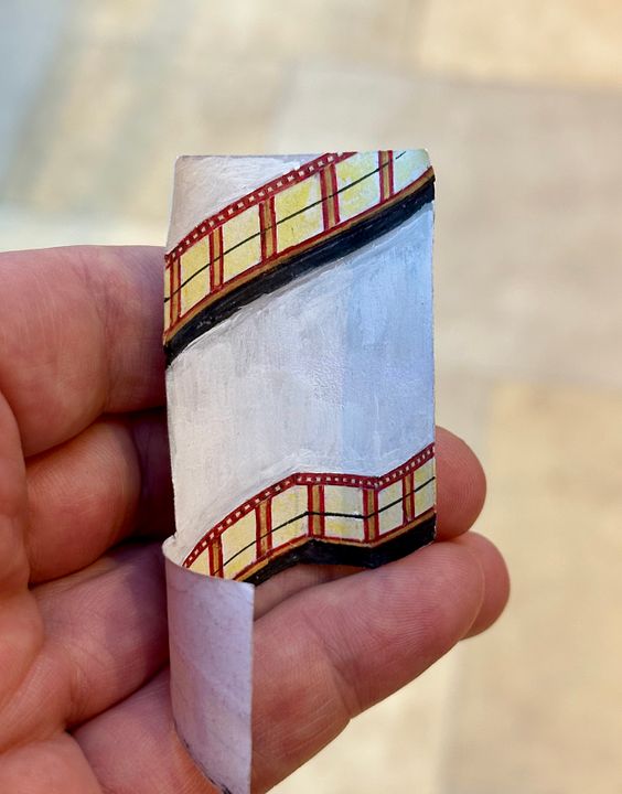
The artwork for the tiles was already available from the station building. Tile strips were cut out and thinned down from behind with a scalpel and tweezers so that they were almost like a transfer. Image
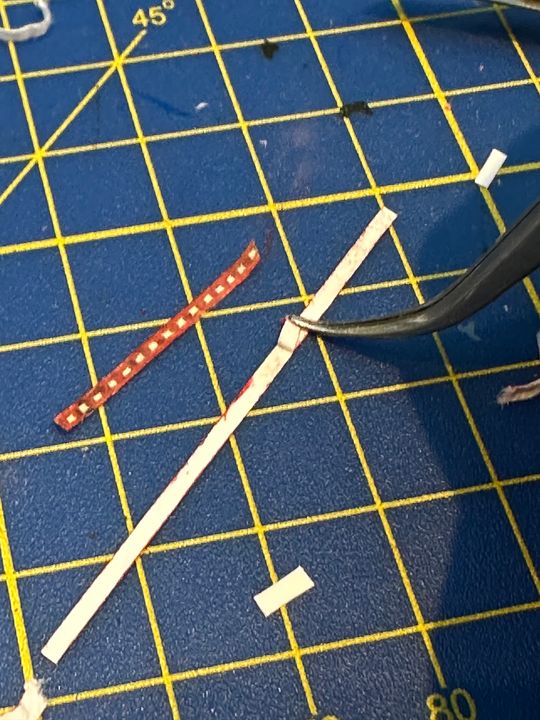
A paper liner was marked up and the individual tile patterns glued into place. I’m sure some clever person could have drawn all this up and printed it, but I’m more of a make it directly sort of person.Image
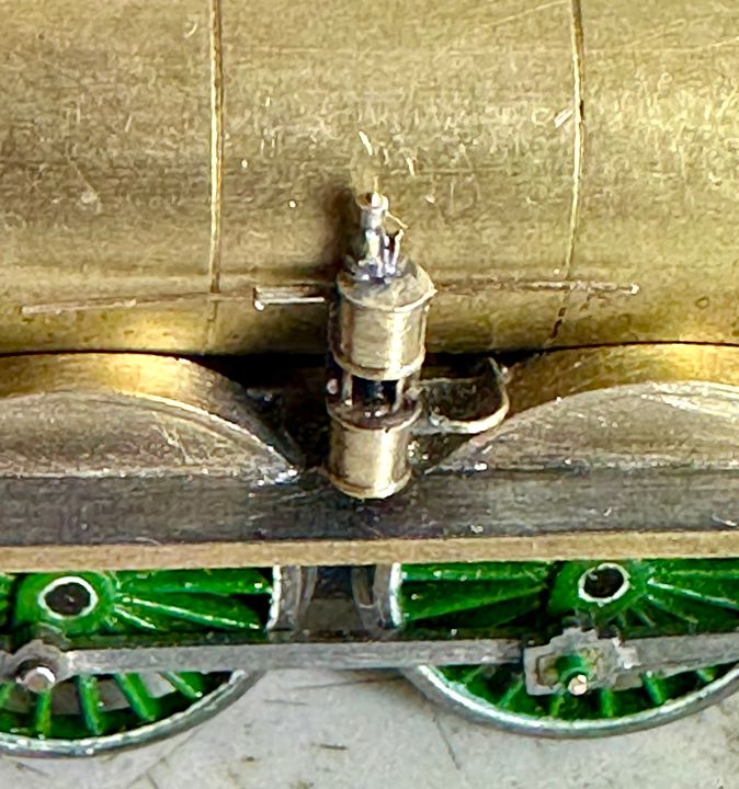
The liner was held in place with photo mount and a chrome metallic pen used to finish the top of the ventilation shaft cone and the top of the main shaft lining. Finally a light cured resin spherical lens was made to go on top of the cone. The reason for this? There is an LED positioned immediately above the main shaft in the roof and these reflective / refractive devices might capture and improve light transmission down the stairwell. I did not want to fiddle with extra LEDS. Image
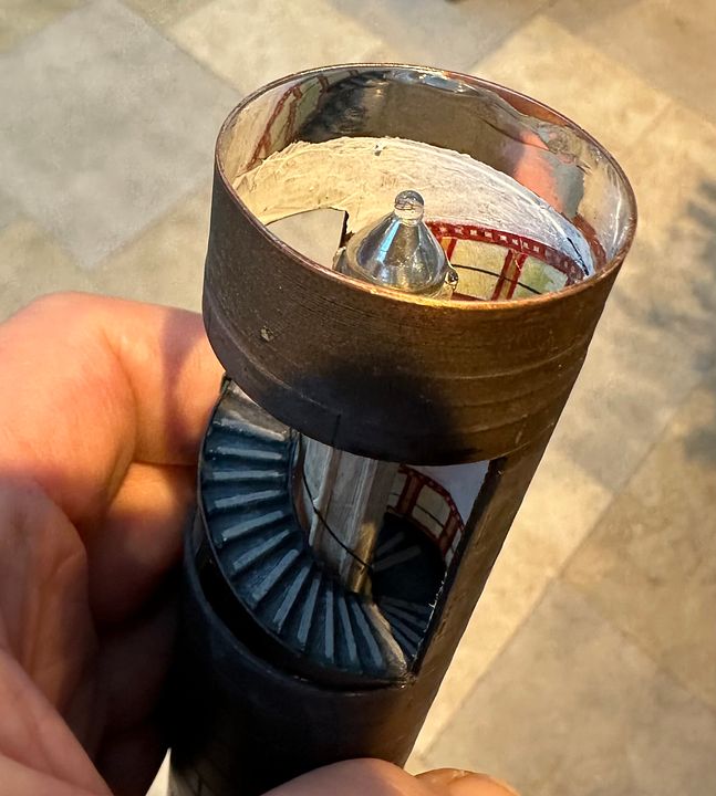
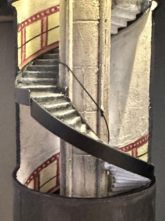
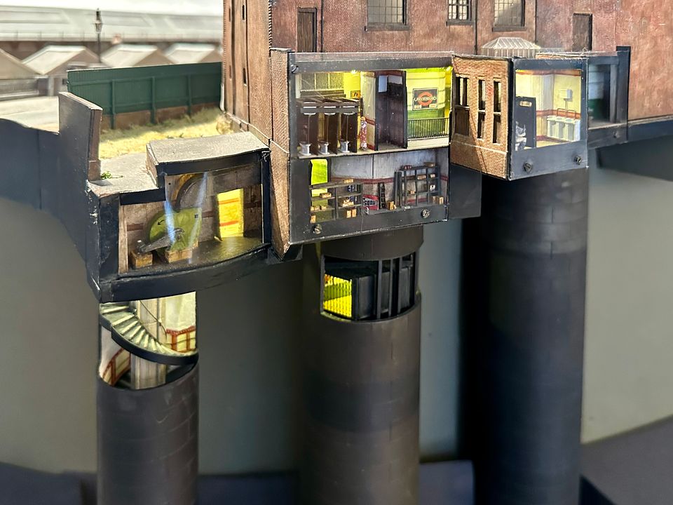
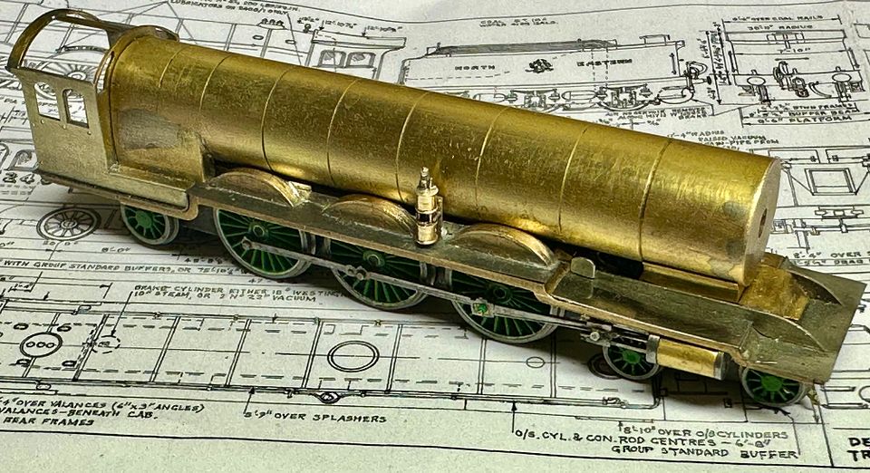
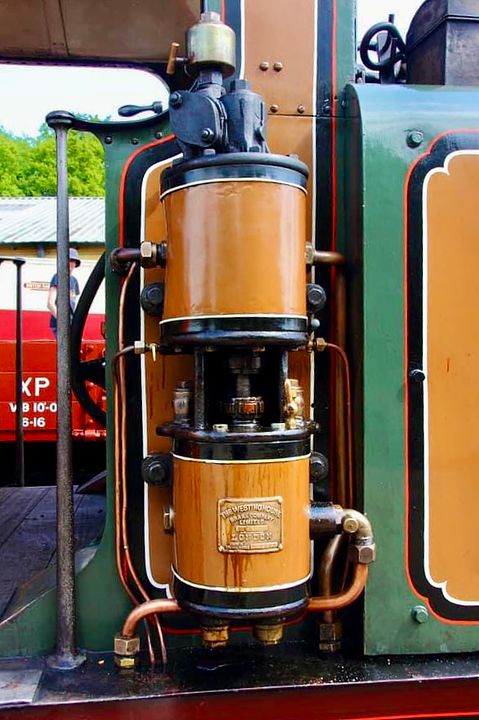
The final scene fulfils the aim we had three years ago of showing how a tube station is laid out. It’s not really realistic modelling, but I’ve found it great fun to do. Image
Just for completeness here is a
link showing the famous Covent Garden steps. https://www.reddit.com/media?url=https% ... 67d3bf2a61 
I think that’s enough tube modelling for a while, apologies for the long post!

Tim
Last edited by Tim Watson on Sat Dec 30, 2023 12:11 pm, edited 1 time in total.
Jim de Griz
NER J27 0-6-0
Posts: 147
Joined: Thu Apr 01, 2021 8:47 pm

Re: Copenhagen Fields & TFW’s workshop

Post by Jim de Griz »

That's is very cool, I love all the little details, the fact they are in N Gauge is even more impressive.

Jim de Griz
drmditch

Re: Copenhagen Fields & TFW’s workshop

Post by drmditch »

Jim de Griz wrote: Thu Dec 28, 2023 11:15 pm That's is very cool, I love all the little details, the fact they are in N Gauge is even more impressive.
N gauge ?
Jim de Griz
NER J27 0-6-0
Posts: 147
Joined: Thu Apr 01, 2021 8:47 pm

Re: Copenhagen Fields & TFW’s workshop

Post by Jim de Griz »

Entirely possible i have my wires crossed, but I thought the model was in 2mm scale?

Jim de Griz
Tim Watson
GER D14 4-4-0 'Claud Hamilton'
Posts: 312
Joined: Mon Oct 24, 2016 11:37 am

Re: Copenhagen Fields & TFW’s workshop

Post by Tim Watson »

I never get fussy about what people call the layout. Life is too short to worry!

Tim
Tim Watson
GER D14 4-4-0 'Claud Hamilton'
Posts: 312
Joined: Mon Oct 24, 2016 11:37 am

Re: Copenhagen Fields & TFW’s workshop

Post by Tim Watson »

I have been working on the splashers for the Raven NER 4-6-2 class over the last few days.  She’s beginning to look a bit more racey, with the wheels covered in a bit.  The gap at the front of the running plate is because the assembly is just resting on the loco. 
Image
The brass disc blanks were turned from a lump of brass in the Myford 254. The front face of the splashers, including the brass rim was finshed on this lathe as can be seen:
Image
Five discs were made and parted off. One as a prototype and two were used. 
Image
The discs were mounted in a step collet on the watch maker’s lathe and hand finish-turned using a graver. Important to note that the graver is held with a pen like grip so that should it ‘catch’ then it flies from your grip, not through your hand. 
Image

https://youtu.be/QnLQHELrKao?si=mOxrnY9to9N6D_l1

The thickness of the splashers was checked using a thickness gauge.
Image
Once happy with the proportions the splashers were cut off as chord segments with a piercing saw. The tops of the running plates were made from 5thou steel, with suitable clearance notched for the wheels. The splashers were rebated at each end so as to locate on the steel when soldering into place.
Image
The engine has a Westinghouse pump on the RHS: that should be fun…

Tim
User avatar
nzpaul
LNER Thompson B1 4-6-0 'Antelope'
Posts: 610
Joined: Sat Sep 24, 2011 11:48 am
Location: New Zealand

Re: Copenhagen Fields & TFW’s workshop

Post by nzpaul »

Superb. Thanks for the lesson on making splashers, I've never thought of turning them from solid rod like that, must try that next time.

Paul
User avatar
Dave
LNER A4 4-6-2 'Streak'
Posts: 1695
Joined: Sat Nov 13, 2010 9:33 pm
Location: Centre of the known universe York

Re: Copenhagen Fields & TFW’s workshop

Post by Dave »

Likewise, thanks for the tip.
Tim Watson
GER D14 4-4-0 'Claud Hamilton'
Posts: 312
Joined: Mon Oct 24, 2016 11:37 am

Re: Copenhagen Fields & TFW’s workshop

Post by Tim Watson »

Just a little more progress on the Skittle Alley today. 
Image
The representation of the prototype frames between the splashers have now been fitted. These were made by soldering a strip along the back of the splashers and then cutting out the unwanted bits with a piercing saw; finally tidying up with a bur, so saving fiddling with small pieces. 
Image
The next item was the bracket for the Westinghouse pump. This  was a very substantial casting in real life.
Image
This photo is of a prototype made with a (too) small brass T section. The end piece is folded over and the junction with the upright pillar flooded with silver solder paste and gently heated to flash into the crack, so making a strong assembly. 
Image
The definitive bracket was made from 3mm brass T section, filed down to size (approx. 2mm wide) with the foot silver soldered in place. A long handle was retained for holding during construction and positioning the bracket on the running plate whilst soldering: I use this technique a great deal for stabilising small pieces during assembly.
Image
The top had been partially cut through so that it simply needed twisting to remove the handle.
Image
I have a cunning plan for making the pump…

Tim
Tim Watson
GER D14 4-4-0 'Claud Hamilton'
Posts: 312
Joined: Mon Oct 24, 2016 11:37 am

Re: Copenhagen Fields & TFW’s workshop

Post by Tim Watson »

After a few hours of fiddling, the basics of the Westinghouse pump on 2400 are now complete. The steam supply & exhaust plumbing will probably be made later, the air delivery pipe rather sooner.
Image
A 2.3mm diameter blank for the cylinders was turned and centre drilled 0.4mm over 5mm depth. Drilling such a deep hole is taken very carefully, with many clearance removals, aided by RTD cutting fluid, and sharp TC drills.
Image
The blank was then finish turned with a graver, giving the raised ends to the cylinders. A piercing saw was used to separate the two cylinders, also making the stuffing box at each end.
 Image
A conventional 0.4mm diameter steel drill shank was used to align the cylinders and a U shaped piece of brass (box section 1.6mm square with a side removed) inserted between the two cylinders - this represents the casting that holds them together on the real thing. The assembly was anointed with silver solder paste and pinned into a stable relationship with old drill shanks thrust into the charcoal block. The whole assembly was gently brought up to red heat for the solder to flash. On a very fine and small component such as this I turn off the workbench lighting so that I can gauge the temperature more easily.
 Image
After pickling in citric acid, a few holes were drilled in the cylinders for the shuttle valve and oiler on the top, compressed air outlet pipe and a slot cut on the back for the steam inlet and exhaust pipes. The drill shank is a very useful handle to hold this rather titchy component.
Image
The mounting bracket on the running plate had been fitted previously (with two holes drilled in it) and this was augmented by a couple of pieces of brass wire which were threaded as one U shaped staple from behind and soldered in place. The excess wire was cut off and dressed in front and behind to neaten them up. 
Image
These two pegs represent some substantial brass bolts in this area and made it easy to locate the pump for soldering to the bracket: the drill shank had previously been sliced off with a diamond disc. Having the main pump silver soldered ensured that it didn’t fall apart when attaching it to the locomotive. 
Image (photo courtesy Owen Chapman)
The final result needs to fit very close to the boiler as the hand rail takes a detour round the top of it! The extra bits for the pump will be made when the associated plumbing is fitted.
 Image
The piston is scarcely visible - like the real thing - but at least I know it’s there. The Association makes a 3DP version of this which is very fine, but I prefer turned metal in this situation. The 3D metal print looks a bit ‘hairy’.  Quite crazy really, as the whole thing is only 6mm tall. 

Tim
Last edited by Tim Watson on Thu Mar 28, 2024 11:15 am, edited 1 time in total.
Jim de Griz
NER J27 0-6-0
Posts: 147
Joined: Thu Apr 01, 2021 8:47 pm

Re: Copenhagen Fields & TFW’s workshop

Post by Jim de Griz »

It is fascinating to see how you create something so intricate from scratch.

Challenger
Tim Watson
GER D14 4-4-0 'Claud Hamilton'
Posts: 312
Joined: Mon Oct 24, 2016 11:37 am

Re: Copenhagen Fields & TFW’s workshop

Post by Tim Watson »

I couldn’t really resist continuing with the Westinghouse pump, so it now has the compressed air pipe fitted and the basic fittings for the steam feed and exhaust. 
Image

The feed pipe fitting was made from some 0.5mm OD brass pipe, soldered into the groove cut in to the back of the steam cylinder. This did not have a large enough bore and so it was reamed out using an 06 endodontic file. These are the smallest used in root canal treatments and are made from nickel titanium alloy. The size represents 0.06mm diameter  measured 1mm from the tip. 
Image
The video clip shows it in action. 

The regulator on the LHS is next to be added and the pipe work can be seen here as a piece of 33swg phosphor bronze wire. 
Image

Having this running plate unit as a separate sub-assembly has made it much easier to work on. Apologies if this post relives dental memories for some!

Tim
Tim Watson
GER D14 4-4-0 'Claud Hamilton'
Posts: 312
Joined: Mon Oct 24, 2016 11:37 am

Re: Copenhagen Fields & TFW’s workshop

Post by Tim Watson »

Now the fun and games can start. Image
This is the beginning of the four doll gantry at the north end of Gasworks Tunnel on the  down lines. Image
There aren’t any decent close up photos of it, but these are the arms that will be modelled. At least two of them should probably work sometime, as they signal a conflicting route, but we’ll see.
Image
Maybe we should just put a steam generator in the tunnels, so they’re hidden, a bit…

Tim
Tim Watson
GER D14 4-4-0 'Claud Hamilton'
Posts: 312
Joined: Mon Oct 24, 2016 11:37 am

Re: Copenhagen Fields & TFW’s workshop

Post by Tim Watson »

There is another signal in the vicinity which is rather fun. Can anyone suggest what the other two positions indicated?
Image
The image also shows step pegs on the nearer dolls and only partial railing on the gantry at high level. The more you look the more you see…

Tim
Hatfield Shed
LNER A4 4-6-2 'Streak'
Posts: 1666
Joined: Fri Dec 23, 2011 3:34 pm

Re: Copenhagen Fields & TFW’s workshop

Post by Hatfield Shed »

Tim Watson wrote: Thu Apr 25, 2024 7:26 pm ...Maybe we should just put a steam generator in the tunnels, so they’re hidden, a bit…
I expect the vote would be overwhelmingly 'want to see it'. There are theatrical smoke generators which might do the job, but I would be concerned for any deposit or condensate on the rails mucking up operational reliability.
Tim Watson wrote: Fri Mar 29, 2024 10:27 am ... Apologies if this post relives dental memories for some!
All of the positive kind, due my family inheritance of a crowded jaw with adult dentition at all angles. Blessed with modern technique and anaesthesia I have had none of the abundant resulting troubles of my forebears. All this, and exquisite model making...
Post Reply