West End Workbench
Moderators: 52D, Tom F, Rlangham, Atlantic 3279, Blink Bonny, Saint Johnstoun, richard
-
Jim de Griz
- H&BR Q10 0-8-0
- Posts: 175
- Joined: Thu Apr 01, 2021 8:47 pm
Re: West End Workbench
Those barnums are awesome. Incredible that you made those handrails by hand.
Jim de Griz
Jim de Griz
-
jwealleans
- LNER A4 4-6-2 'Streak'
- Posts: 4276
- Joined: Wed Oct 25, 2006 8:46 am
Re: West End Workbench
Thnaks, Jim. It's thanks to Dave S, actually: he sent me the artwork for some etched ones he did and I was able to use that as a template for bending.
- Atlantic 3279
- LNER A4 4-6-2 'Streak'
- Posts: 6635
- Joined: Fri Jun 26, 2009 9:51 am
- Location: 2850, 245
Re: West End Workbench
Most commendable handrail scrolling, especially in view of the tedium and the effect on eyesight which was bad enough when I did mine at the age of forty-something, and I hadn't recently had Covid.
More fun still if you use a soldered T-joint instead of the upper knob...
More fun still if you use a soldered T-joint instead of the upper knob...
Most subjects, models and techniques covered in this thread are now listed in various categories on page1
Dec. 2018: Almost all images that disappeared from my own thread following loss of free remote hosting are now restored.
Dec. 2018: Almost all images that disappeared from my own thread following loss of free remote hosting are now restored.
-
jwealleans
- LNER A4 4-6-2 'Streak'
- Posts: 4276
- Joined: Wed Oct 25, 2006 8:46 am
Re: West End Workbench
Small steps.... especially risky if you still have a cough and end up shoving the iron through the side.More fun still if you use a soldered T-joint instead of the upper knob...
Day off today, so before I escort Lady W to the seaside this afternoon, I've started another carriage. This is the seventh for the Easterling set for Wickham Market and appropriately enough is a Diagram 7. This seems to be the less common Gresley Composite, 2 1/2 - 5 instead of the seemingly much more in demand 3 1/2-4. Oddly there was one of each in the Lowestoft portion. I'm sure there was a good reason for it at the time.
I haven't done a detailed carriage build for a while, so let's take a good look at this one. Here are the components laid out just now:
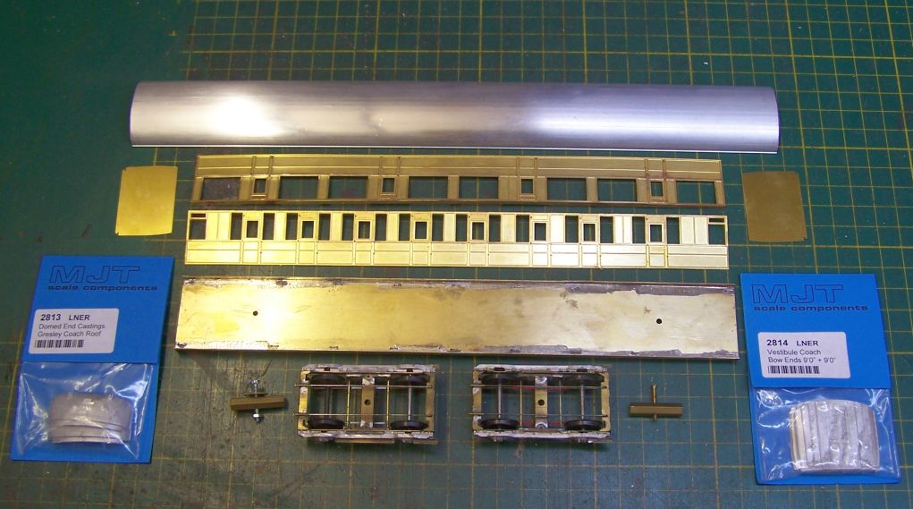
MJT roof - shan't cut that to length until the body is built. MJT ends for it are bottom left.
Sides are from Bill Bedford's etched list, though I've had these a while. These come in two halves which are soldered together at the waist. Bottom hinge holes are etched in, the top ones just have a witness mark so I've drilled those through .5mm and will slot them in due course. I have added a strip of etch along the top at right angles to the side to make them more rigid and the next job will be to bend in the turnunder.
The ends are broken off the MJT floor. I build my carriages to split at the solebar in the Comet and D & S manner, so those ends have to come off.
MJT floor, made up per the instructions up to this point. It will have to be altered for body fixing in due course. I've drilled holes for the bogie screws as i'm not using MJT bogies on this set.
Finally Mitchell - Pendleton bogies and hexagonal bolsters. I acquired a number of these bogies on built Gresleys and initially just put them to one side, replacing with MJT for the Grantham stock. They're advertised as made for EM/P4 use, so i didn't really consider them. However, on examination it looked to be very easy to adapt them for OO and so that's what will happen. They're very free running and this set was initially intended to be hauled by an RTR loco (Hornby B1/B17) so I wanted to give it a fighting chance. As it happens I've acquired a NuCast B1 which may end up being used, but it would be nice to have multiple options.
-
jwealleans
- LNER A4 4-6-2 'Streak'
- Posts: 4276
- Joined: Wed Oct 25, 2006 8:46 am
Re: West End Workbench
Progress this evening. The hinge holes in the sides are opened out with the point of a fine file so that the scrap etch we'll be using for the hinges will pass through. This is much easier to do when the sides can still be in the flat.
Next the turnunder is applied. I have a tool for this.
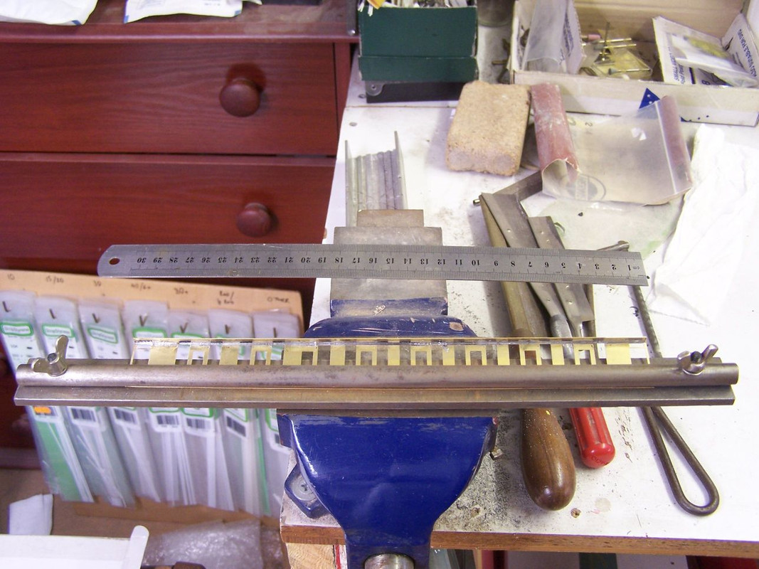
I claim no credit, the design is copied from one Tony Wright uses and it was made for me by an engineering friend as a favour. The bottom of the side is clamped under the rod and the side bent up with the ruler. You don't need much of a bend, but the sides have a tendency to spring back flat, especially in the centre, so I err on the side of over bending - it's easy to flatten it out again between finger and thumb. I always assemble sides fully before doing this - I know MJT instructions suggest bending the panels before attaching to the sides, but you never get the same degree of bend on both and it makes a fiddly job even fiddlier.
Once the sides are suitably curved, they can be attached to the ends.
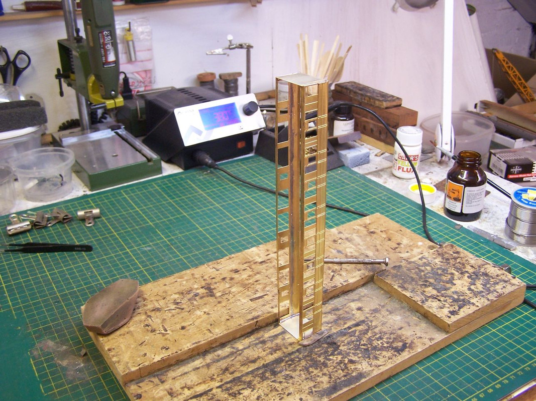
The brass end goes inside the side, so you may have to notch the top return back slightly to allow that to happen. The final assembly needs to be square but again is easily bent gently into alignment with finger pressure. If it's too resistant, hold it in place and remelt the solder until it goes where it needs to.
Can you tell what it is yet?
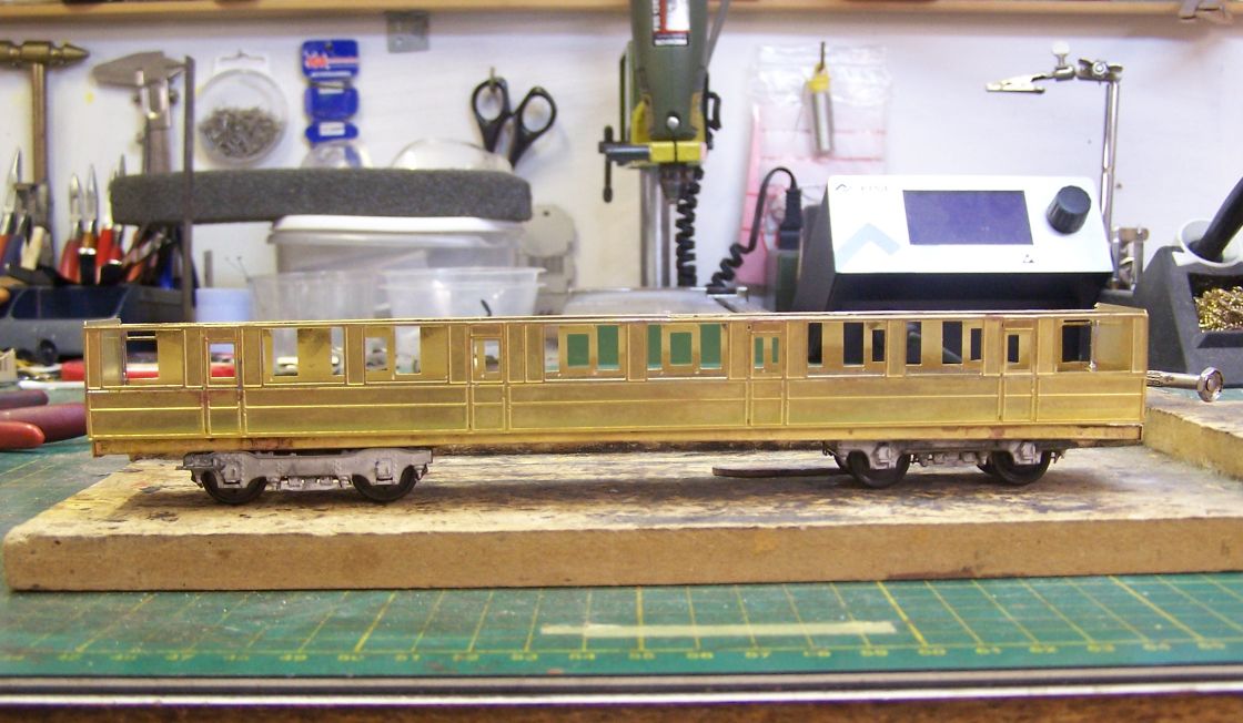
Posing the bits together makes me feel as though I'm making progress, but also serves to check that everything fits. To sit the body onto the underframe as here I've removed the end 10mm of the underframe side at each end. That would have to be done anyway in advance of the next step, which will be to fasten sides and underframe together.
Next the turnunder is applied. I have a tool for this.

I claim no credit, the design is copied from one Tony Wright uses and it was made for me by an engineering friend as a favour. The bottom of the side is clamped under the rod and the side bent up with the ruler. You don't need much of a bend, but the sides have a tendency to spring back flat, especially in the centre, so I err on the side of over bending - it's easy to flatten it out again between finger and thumb. I always assemble sides fully before doing this - I know MJT instructions suggest bending the panels before attaching to the sides, but you never get the same degree of bend on both and it makes a fiddly job even fiddlier.
Once the sides are suitably curved, they can be attached to the ends.

The brass end goes inside the side, so you may have to notch the top return back slightly to allow that to happen. The final assembly needs to be square but again is easily bent gently into alignment with finger pressure. If it's too resistant, hold it in place and remelt the solder until it goes where it needs to.
Can you tell what it is yet?

Posing the bits together makes me feel as though I'm making progress, but also serves to check that everything fits. To sit the body onto the underframe as here I've removed the end 10mm of the underframe side at each end. That would have to be done anyway in advance of the next step, which will be to fasten sides and underframe together.
-
jwealleans
- LNER A4 4-6-2 'Streak'
- Posts: 4276
- Joined: Wed Oct 25, 2006 8:46 am
Re: West End Workbench
Last rites at Scottiedog's today, but I did manage some progress this morning before going. First step here is to make the end plates which the fixing nuts will attach to.
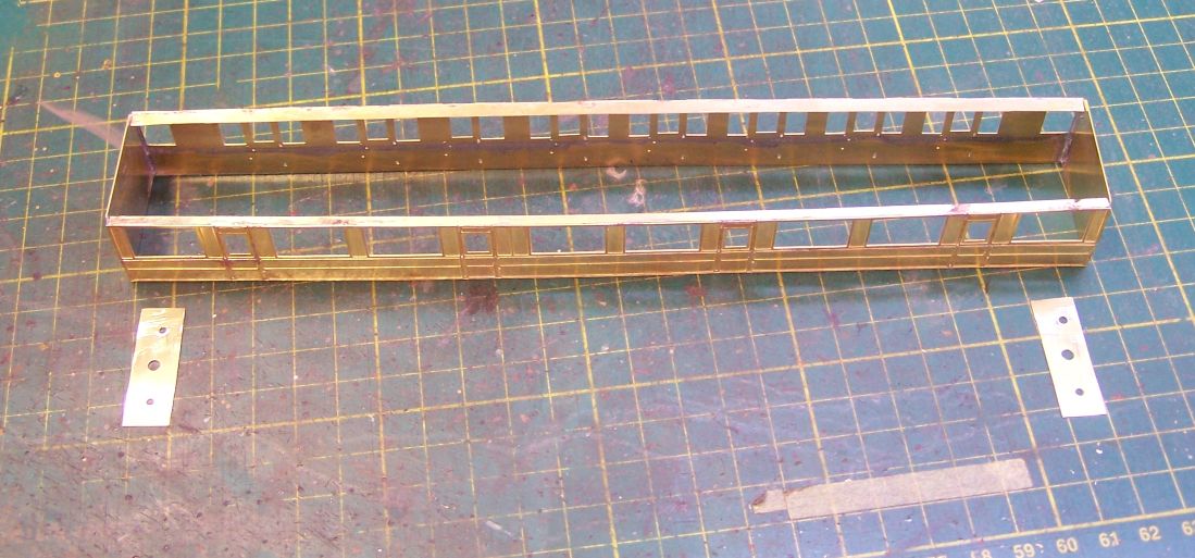
These are scrap etch cut to approximate size then filed down to a snug fit. Width isn't terribly important here, but setting the body screws a little way in from both sides and ends will mean it's a bit less crowded under there, especially if you're fitting sprung buffers. The centre hole is for the coupling attachment. 10BA for the two fixing screws and 8BA for the coupling. I usually use Bill Bedford etched couplings on coaches but in making stock for Grantham I have found that an 8BA bolt will also work for a Kadee with a 252 gearbox. Other couplings may be available.
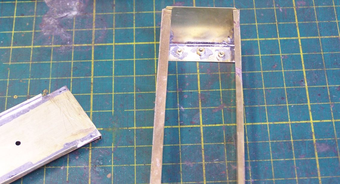
Nuts are soldered to the plate and the whole thing then soldered into the body. Keeping it a very snug fit makes this process quicker and so it's less likely you'l melt the existing joints and lose a nut. Do test the clearances on each nut before you solder the plate into the body, it's much easier to adjust them while the plate is free.
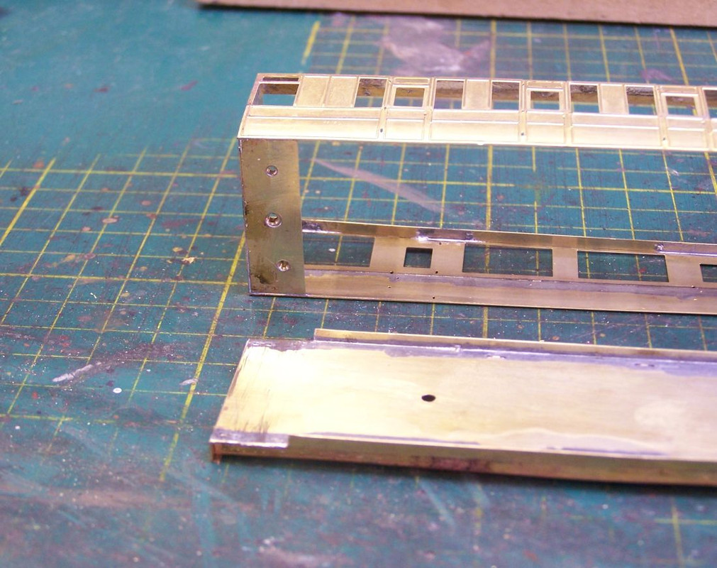
Now the body is ready to be offered up to the floor assembly, making sure it fits over the small lip without fouling and sits squarely length and width ways.

These are scrap etch cut to approximate size then filed down to a snug fit. Width isn't terribly important here, but setting the body screws a little way in from both sides and ends will mean it's a bit less crowded under there, especially if you're fitting sprung buffers. The centre hole is for the coupling attachment. 10BA for the two fixing screws and 8BA for the coupling. I usually use Bill Bedford etched couplings on coaches but in making stock for Grantham I have found that an 8BA bolt will also work for a Kadee with a 252 gearbox. Other couplings may be available.

Nuts are soldered to the plate and the whole thing then soldered into the body. Keeping it a very snug fit makes this process quicker and so it's less likely you'l melt the existing joints and lose a nut. Do test the clearances on each nut before you solder the plate into the body, it's much easier to adjust them while the plate is free.

Now the body is ready to be offered up to the floor assembly, making sure it fits over the small lip without fouling and sits squarely length and width ways.
-
jwealleans
- LNER A4 4-6-2 'Streak'
- Posts: 4276
- Joined: Wed Oct 25, 2006 8:46 am
Re: West End Workbench
I see Dave has already posted some photos, so let's take a break from coachbuilding to look at Ingleby for the last time in this form. A few overall views to start with:
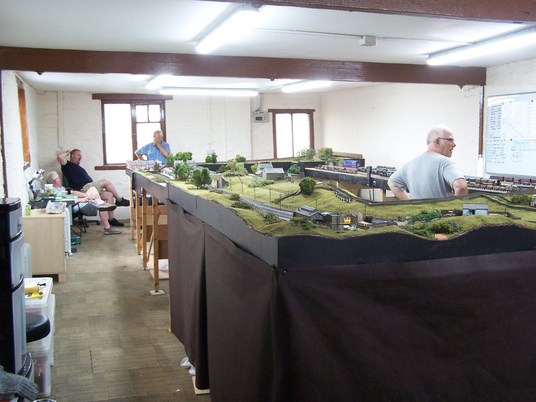
An all-too-familiar sight - Dale in full flow. Scottiedog seated to the left, Norman Venus standing. Mr Jobling out of sight behind the layout and Paul doing all the work.
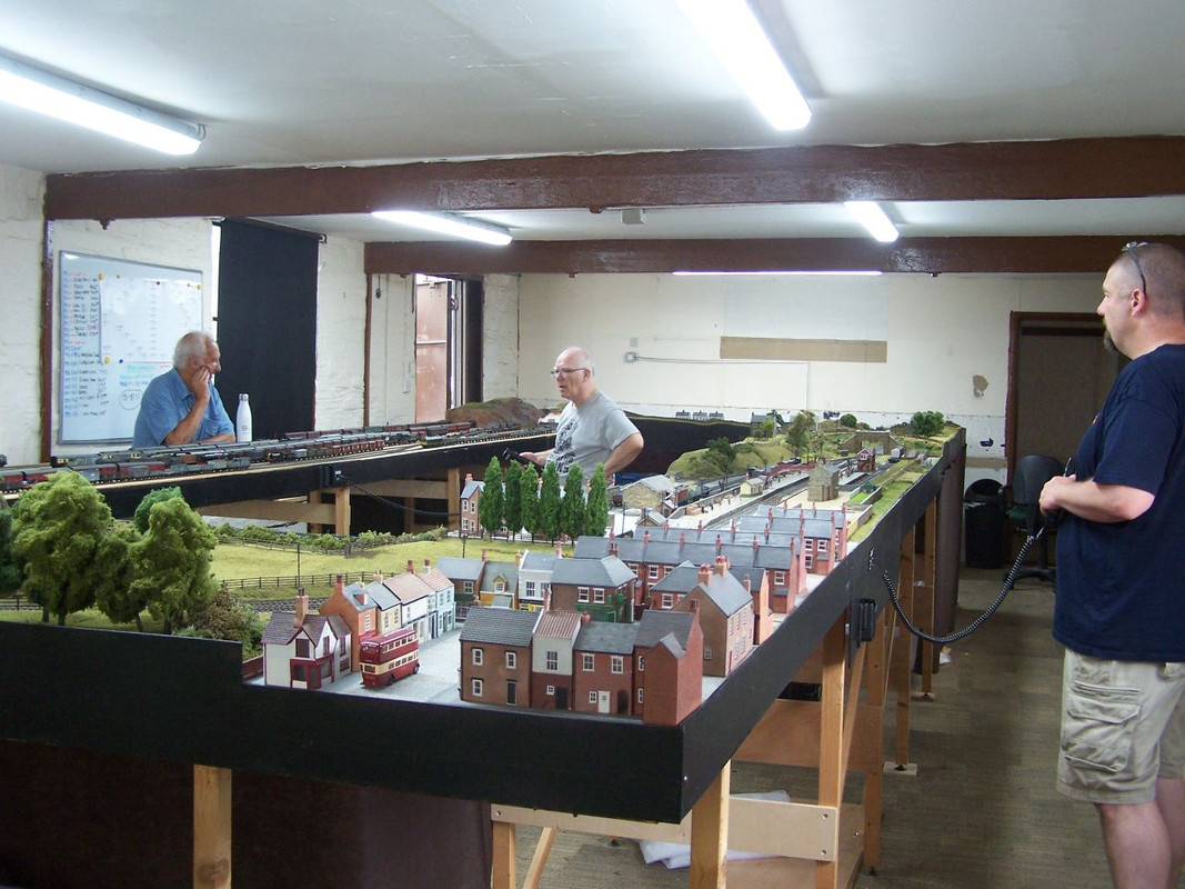
Whatever it was was seemingly still a problem - there were one or two glitches caused by heat closing up track gaps and there was a fair bit of grovelling underneath going on earlier.
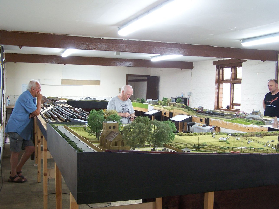
Seems to be working now. Dave Furmage to right. Brad had left to do his shopping by this time.
The curved end boards have been found a new home for reuse, I gather and the straight boards will become the new end to end layout in due course.
I took a box full of wagons to run, the output from the last few months which hasn't gone into boxes yet. Some of them are part weathered as I am doing a demonstration at Thirsk Show on July 30th and intend to use that to finish them off. I'm pleased to say that all of them ran well.
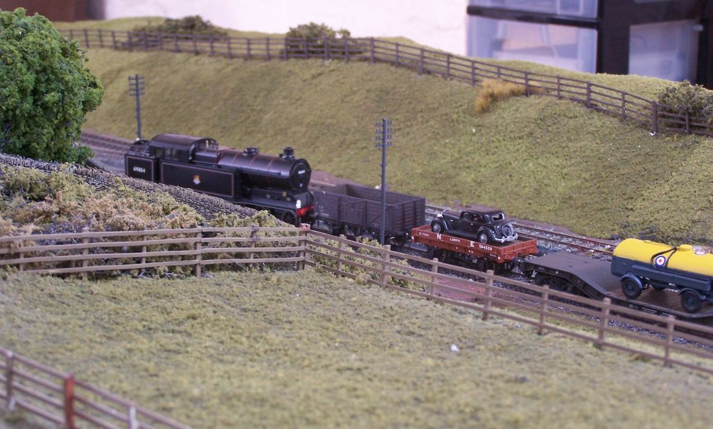
Brad Seaman brought a Sonic A5 which we used to shunt for a while.
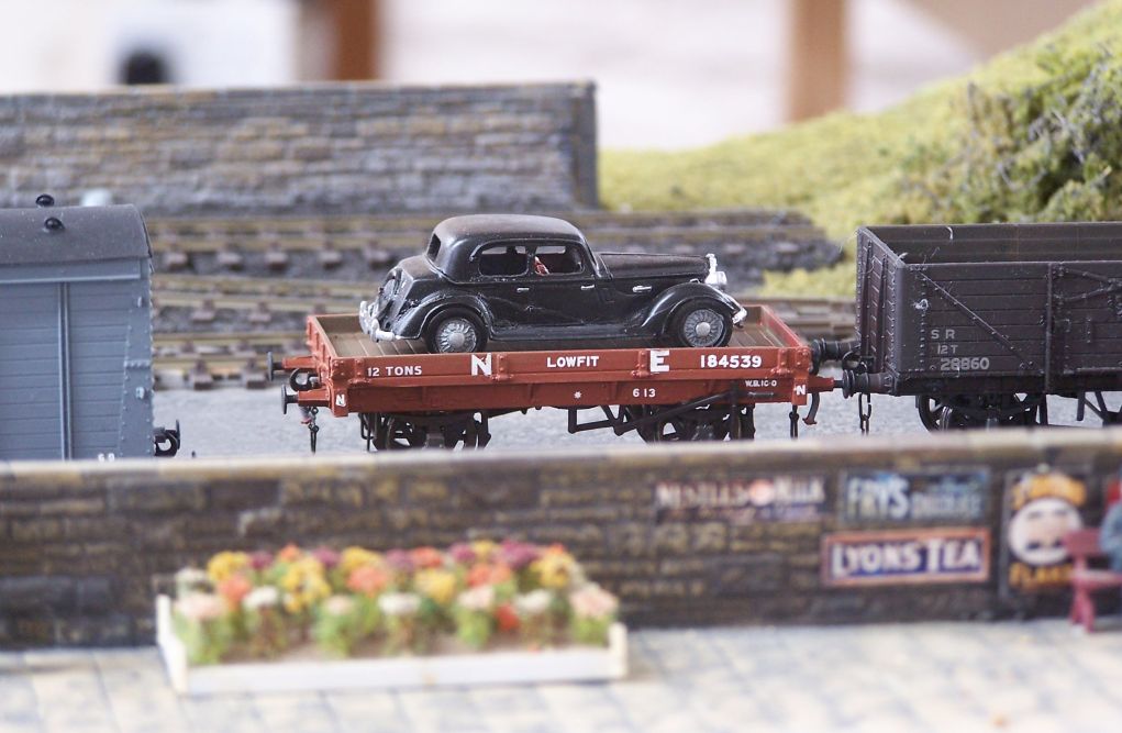
Bachmann Lowfit with Parkside underframe. Can't recall whose kit the car is - it may have just been in a plastic bag when I acquired it.
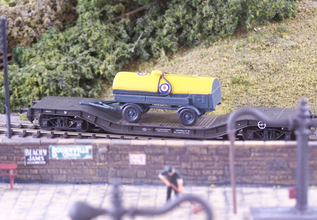
Bowser on Warwell. As with the Lowfit above, both need to be weathered before one can be secured to the other.
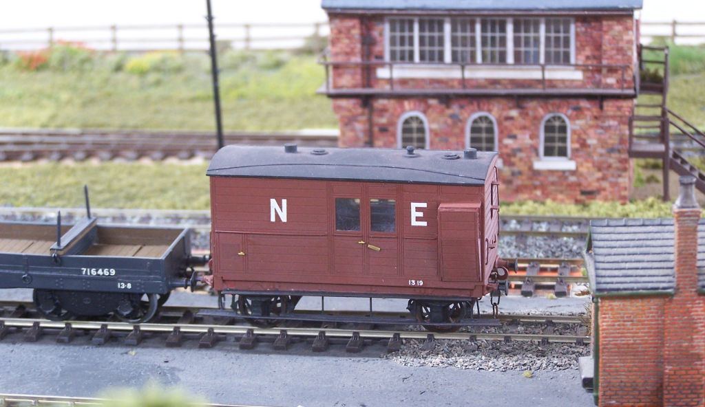
There was a bit of a North British theme in the stock. I can't recall who did the etches for this brake van, it was just something a bit different which I fancied at the time. It doesn't get out much so it was nice to give it a run.
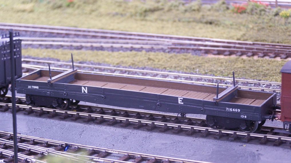
This doesn't get out much either as it lives in my wagon building demo box. Hurst Nelson build for the NB (I have a feeling they were called gondolas). It's made from a Parkside NE quad.
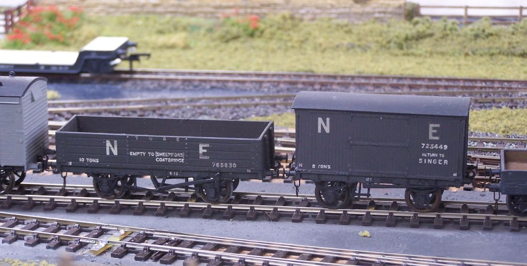
These were both from the club stand at Newcastle show last November, built but not finished.
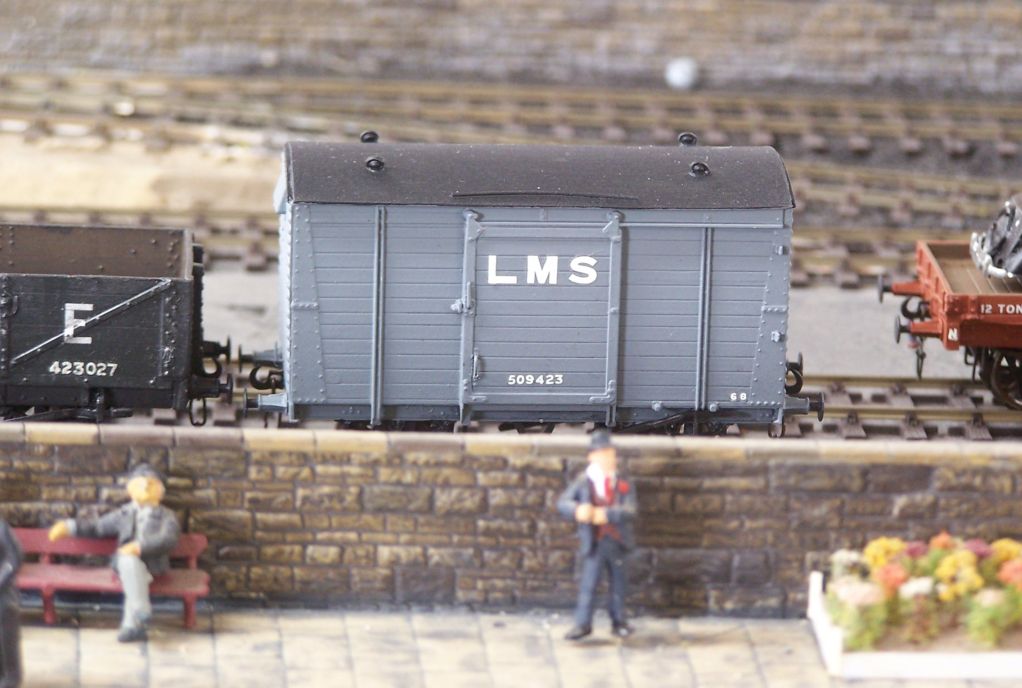
Ratio van from a collection I helped dispose of recently. This has simply been repainted and wire handrails made.
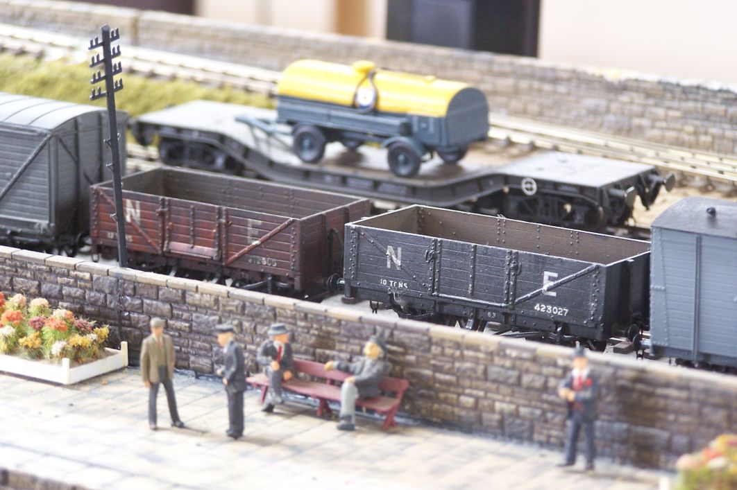
ABS ofit and a GN open which came from the stand at Newcastle.
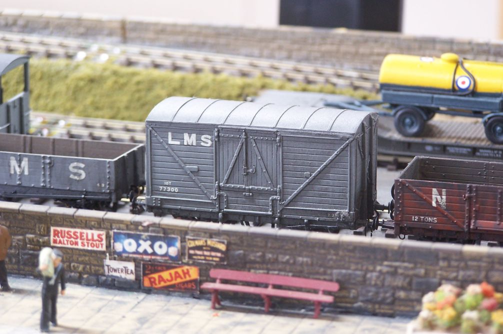
LNWR van by Dave Geen. This came from Brian at 247 Developments.
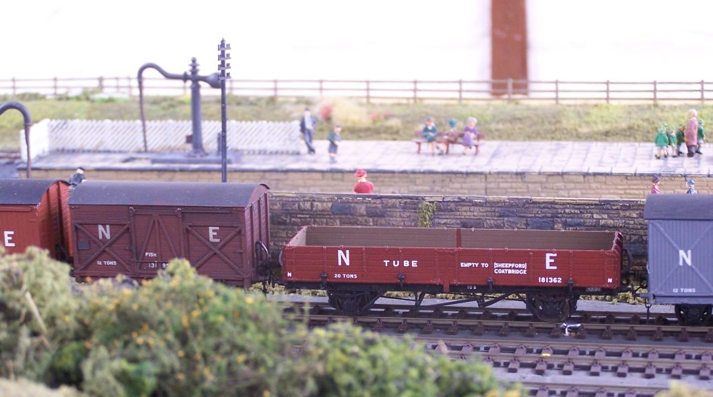
ABS fish from Newcastle and the PMK Tube which was a gift from Jesse Sim.
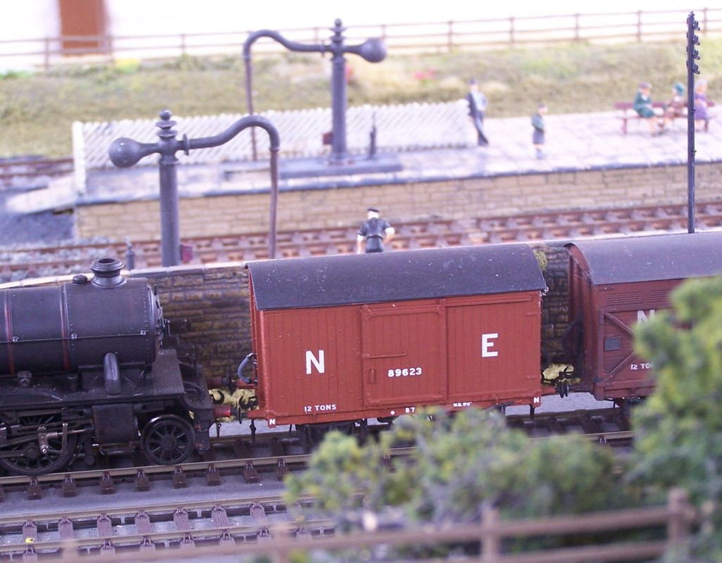
PD LNER vanfit with 9' underframe.
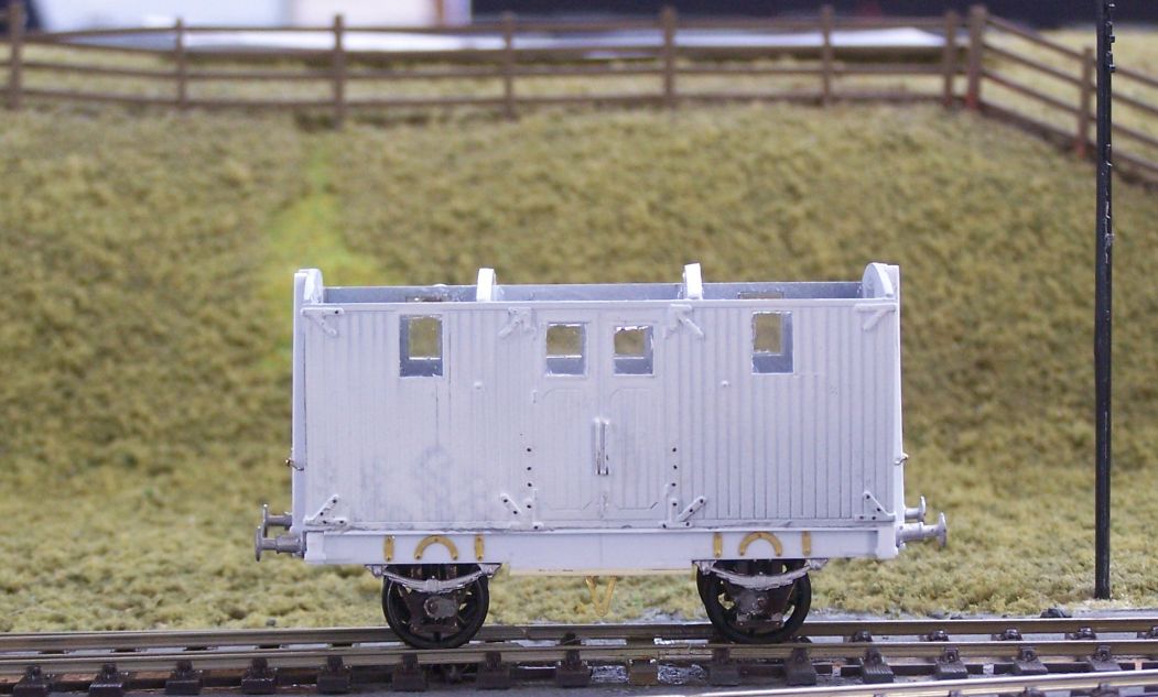
Mr Jobling brought some stock along as well - this is the scratchbuilt Pooley weighbridge van you can see on his thread.
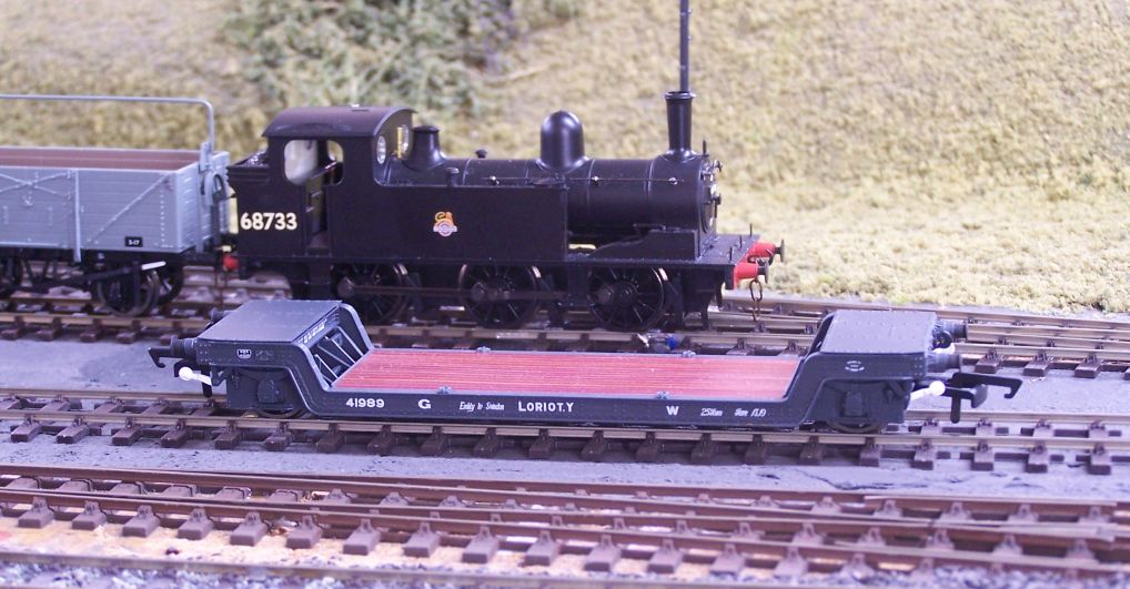
This Loriot is by Hornby, I'm told. It's a lovely thing, but I had to sit down when they told me how much they cost. It's getting much cheaper to build your own again.

An all-too-familiar sight - Dale in full flow. Scottiedog seated to the left, Norman Venus standing. Mr Jobling out of sight behind the layout and Paul doing all the work.

Whatever it was was seemingly still a problem - there were one or two glitches caused by heat closing up track gaps and there was a fair bit of grovelling underneath going on earlier.

Seems to be working now. Dave Furmage to right. Brad had left to do his shopping by this time.
The curved end boards have been found a new home for reuse, I gather and the straight boards will become the new end to end layout in due course.
I took a box full of wagons to run, the output from the last few months which hasn't gone into boxes yet. Some of them are part weathered as I am doing a demonstration at Thirsk Show on July 30th and intend to use that to finish them off. I'm pleased to say that all of them ran well.

Brad Seaman brought a Sonic A5 which we used to shunt for a while.

Bachmann Lowfit with Parkside underframe. Can't recall whose kit the car is - it may have just been in a plastic bag when I acquired it.

Bowser on Warwell. As with the Lowfit above, both need to be weathered before one can be secured to the other.

There was a bit of a North British theme in the stock. I can't recall who did the etches for this brake van, it was just something a bit different which I fancied at the time. It doesn't get out much so it was nice to give it a run.

This doesn't get out much either as it lives in my wagon building demo box. Hurst Nelson build for the NB (I have a feeling they were called gondolas). It's made from a Parkside NE quad.

These were both from the club stand at Newcastle show last November, built but not finished.

Ratio van from a collection I helped dispose of recently. This has simply been repainted and wire handrails made.

ABS ofit and a GN open which came from the stand at Newcastle.

LNWR van by Dave Geen. This came from Brian at 247 Developments.

ABS fish from Newcastle and the PMK Tube which was a gift from Jesse Sim.

PD LNER vanfit with 9' underframe.

Mr Jobling brought some stock along as well - this is the scratchbuilt Pooley weighbridge van you can see on his thread.

This Loriot is by Hornby, I'm told. It's a lovely thing, but I had to sit down when they told me how much they cost. It's getting much cheaper to build your own again.
-
jwealleans
- LNER A4 4-6-2 'Streak'
- Posts: 4276
- Joined: Wed Oct 25, 2006 8:46 am
Re: West End Workbench
Right, back to the serious stuff. The body is positioned on the floor and the captive nuts used to mark the fixing holes. At this point you need to mark one end so you know which way to assemble it. It'll almost certainly only fit one way, but you'll save time if there's a guide.
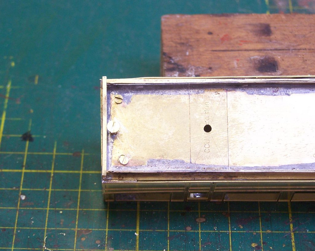
I drill the holes more or less right size then ease them with a file until everything fits smoothly. This gives you a bit of flexibility if the marks haven't been quite right - you can see that I've had to extend the bottom fixing screw hole downwards to allow it to find the nut. I also had to move the 8BA nuts closer to the end to allow the couplings to swing. That was done by unsoldering them, extending the hole towards the end and then reattaching to the end plate while it remained in situ.
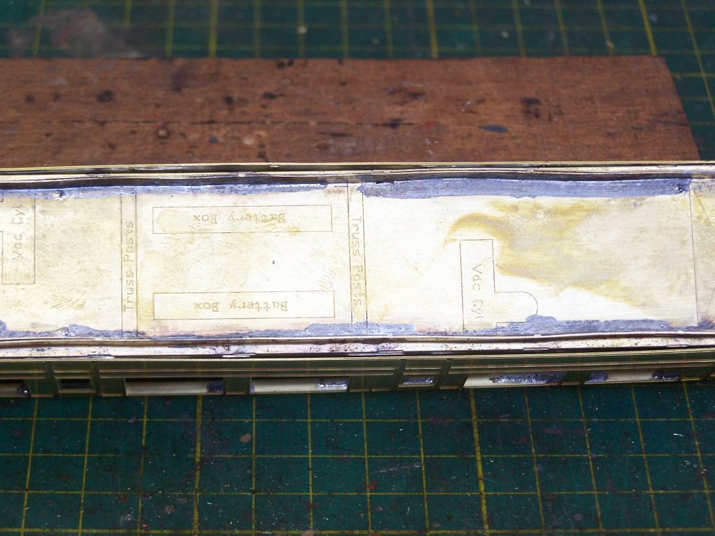
It had been commented on RMWeb that the sides had bowed out. This shows you how far - about 1mm each side. Once the roof is attached the side will be pulled in, but I have since added a piece of etch in the middle just to hold it in the right shape.
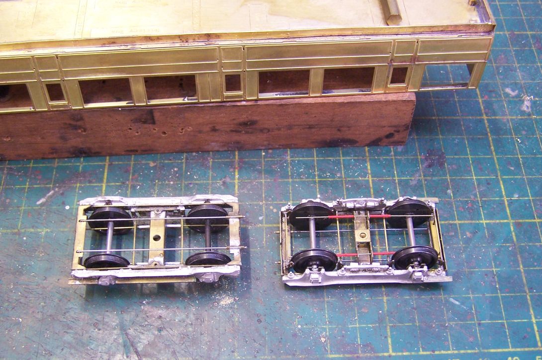
The main job tonight was to regauge the bogies. Here they are from above and below. These bogies are double sprung - the bolster (1/8" hex rod) rests on a pair of wires either side of the fixing bolt. Each axle end is then in a sprung bearing and the exles are retained by a further pair of wires underneath. They are very free running - I don't know enough physics to understand why, but empirically speaking, when trying to get white metal wagons to run freely, sprung ones run much better than those with conventional brass W irons, even rocking ones.
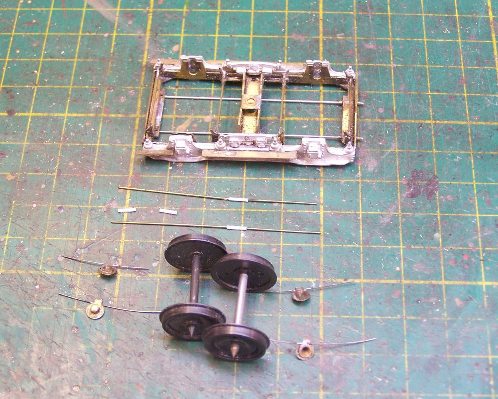
Here's a bogie in pieces. Hopefully that makes it clear how it works. The axle retaining wires are the ones which need moving. They pass through etches holes in the central bolster and are too far apart to allow OO wheels to run.
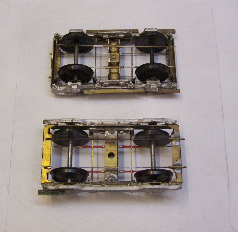
All i do is solder in pieces of .5mm ID tube to hold the wires. There's even a convenient shoulder on the etched bogie to butt them up against. Other than that I haven't had to do anything to the bogies themselves. I'm reusing the EM wheels, suitably adjusted. Wickham Market uses Code 75 track, so I'm hoping I can get away with them on that.
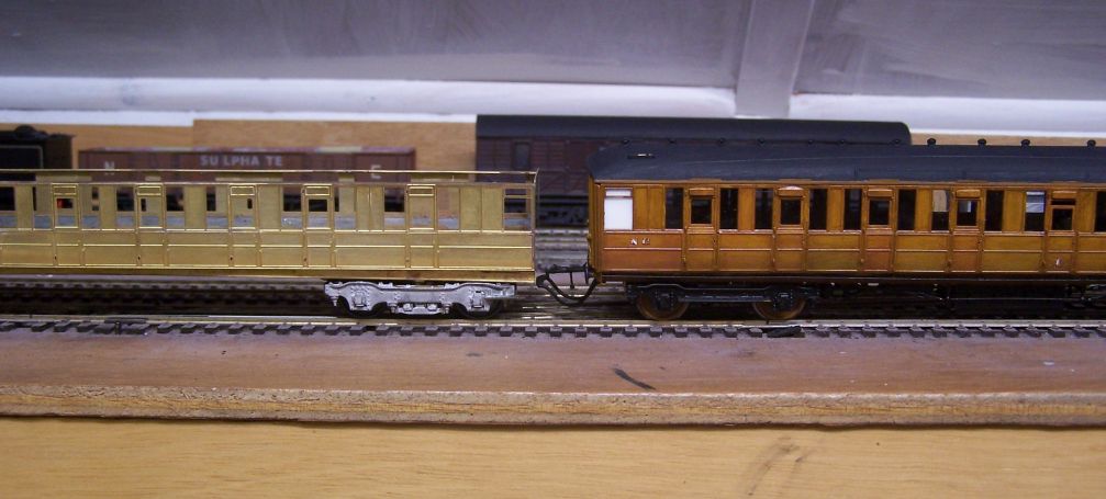
It's good to be able to put the thing together and see it roll, that feels like progress. Here it's next to the adjacent vehicle in the set, a D130 Composite, having the running height checked. Seems to be pretty good at this stage. Hinges next, so there'll be little visible progress for a couple of evenings.

I drill the holes more or less right size then ease them with a file until everything fits smoothly. This gives you a bit of flexibility if the marks haven't been quite right - you can see that I've had to extend the bottom fixing screw hole downwards to allow it to find the nut. I also had to move the 8BA nuts closer to the end to allow the couplings to swing. That was done by unsoldering them, extending the hole towards the end and then reattaching to the end plate while it remained in situ.

It had been commented on RMWeb that the sides had bowed out. This shows you how far - about 1mm each side. Once the roof is attached the side will be pulled in, but I have since added a piece of etch in the middle just to hold it in the right shape.

The main job tonight was to regauge the bogies. Here they are from above and below. These bogies are double sprung - the bolster (1/8" hex rod) rests on a pair of wires either side of the fixing bolt. Each axle end is then in a sprung bearing and the exles are retained by a further pair of wires underneath. They are very free running - I don't know enough physics to understand why, but empirically speaking, when trying to get white metal wagons to run freely, sprung ones run much better than those with conventional brass W irons, even rocking ones.

Here's a bogie in pieces. Hopefully that makes it clear how it works. The axle retaining wires are the ones which need moving. They pass through etches holes in the central bolster and are too far apart to allow OO wheels to run.

All i do is solder in pieces of .5mm ID tube to hold the wires. There's even a convenient shoulder on the etched bogie to butt them up against. Other than that I haven't had to do anything to the bogies themselves. I'm reusing the EM wheels, suitably adjusted. Wickham Market uses Code 75 track, so I'm hoping I can get away with them on that.

It's good to be able to put the thing together and see it roll, that feels like progress. Here it's next to the adjacent vehicle in the set, a D130 Composite, having the running height checked. Seems to be pretty good at this stage. Hinges next, so there'll be little visible progress for a couple of evenings.
-
jwealleans
- LNER A4 4-6-2 'Streak'
- Posts: 4276
- Joined: Wed Oct 25, 2006 8:46 am
Re: West End Workbench
Got the wind right into my sails tonight and the hinges are all attached. To be fair there are only 36 - it's not like doing a quad-art or something equally masochistic.
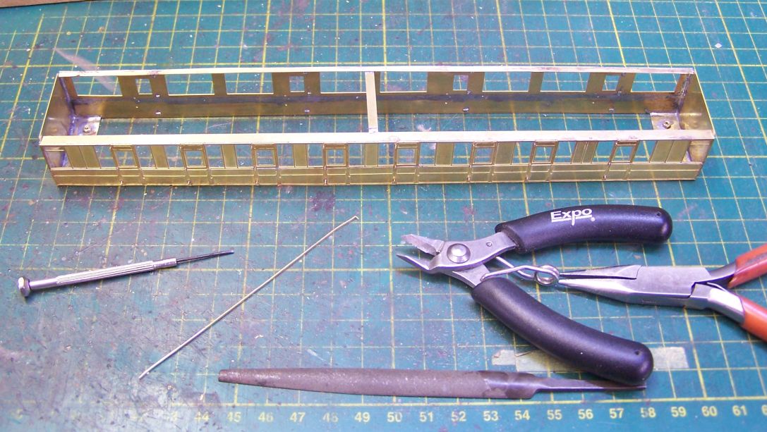
This is all you need - a strip of scrap etch, cutters, pliers, a small file and a small screwdriver. The etch is bent over at the end to give the solder more of a land to grab on to. Where space is very tight I might just poke the etch through the hole and solder it, but you have more chance of them falling off. The file is for tapering the etch to go through the hole, the pliers for bending and gripping and the cutters are self-explanatory. The screwdriver is to space the cutters off the body on the bottom hinge so they're a consistent length. I'll use a very small file to dress the cut ends and the pliers to straighten them up at the next session.
One thing to remember is to keep the area behind the windows as clear of solder as you can and clean off any which wanders. It's easy enough when it's like this, but when the roof is on and the whole thing is painted, you'll thank yourself for leaving a smooth flat surface for the glazing to stick to.
-
jwealleans
- LNER A4 4-6-2 'Streak'
- Posts: 4276
- Joined: Wed Oct 25, 2006 8:46 am
Re: West End Workbench
With all the hot soldering now finished on the body, it's time to start on the low melt. Ends and roof ends, castings on an MJT build of course and which give a satisfying weight to the finished article.
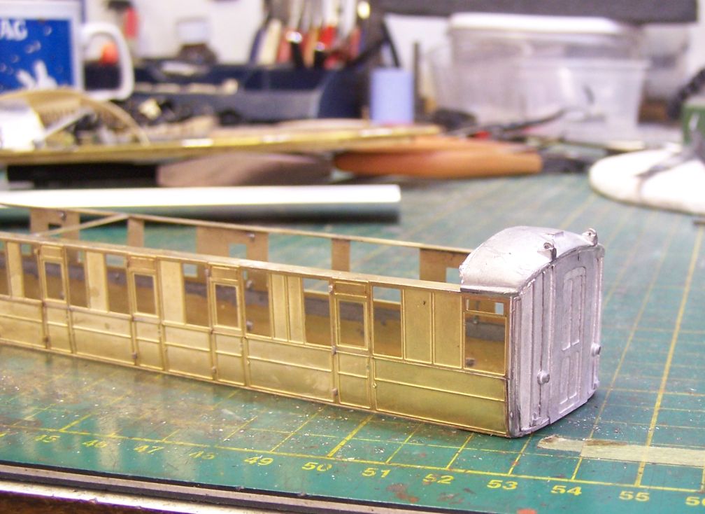
I have heard that Dart are looking at a different approach to the Gresley roof. It is a fact that despite much filing and bending, it is not possible to get the end dome casting to sit with the cornice at anything but a jaunty angle. Once the aluminium centre section is in place there'll be more filing and filling to straighten the whole affair.
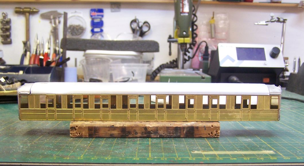
Once the two end domes are fixed the roof can be measured and cut. Cut slightly overlength and file down to a very snug fit, that'll save you some filling and sanding later. I managed to cut at a slight angle so I will have some work to do there. You can also see the step down from the aluminium to the cast end. Dress this down with a file while the roof is not yet attached, this will also save filling and sanding work later.
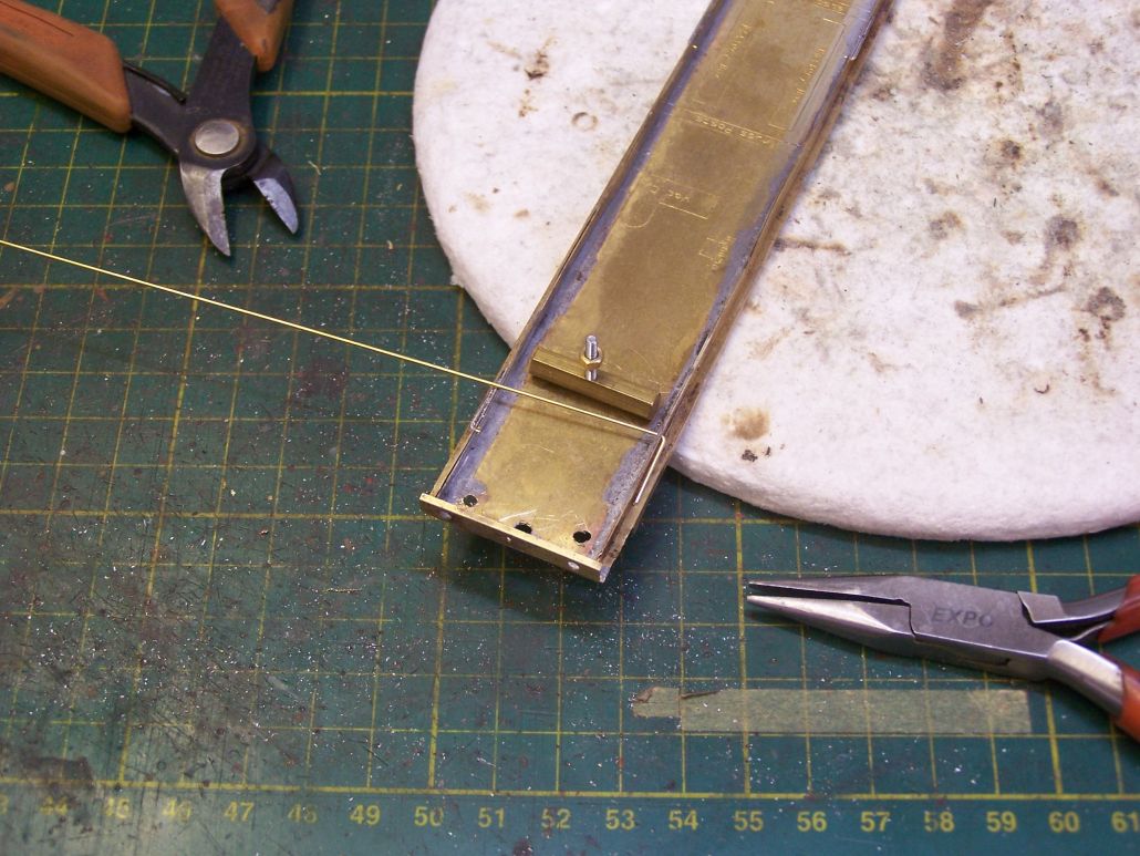
Back to the underframe next and a method I've adopted since I started building coaches for exhibition use. Underframe steps can be very vulnerable to bending or breaking off with handling, so I put lengths of .7mm wire underneath the step to give more surface to solder to. This is done by drilling a .75 hole just above the solebar flange, putting a bent length of .7mm wire through it as above, then soldering in place. The tail can be snipped off and dressed back so it doesn' t interfere with the trussing. For a full length step I use one at each end and one in the middle. I've been doing this for some time and no-one has ever commented on it as it's all but ivisible on the finished vehicle. I did have a slight pause as I was looking at photographs of D7s and the first one I found had individual steps under each compartment door. I think that may have been a wartimne economy measure, though, as thankfully all the others had a continuous step as here.
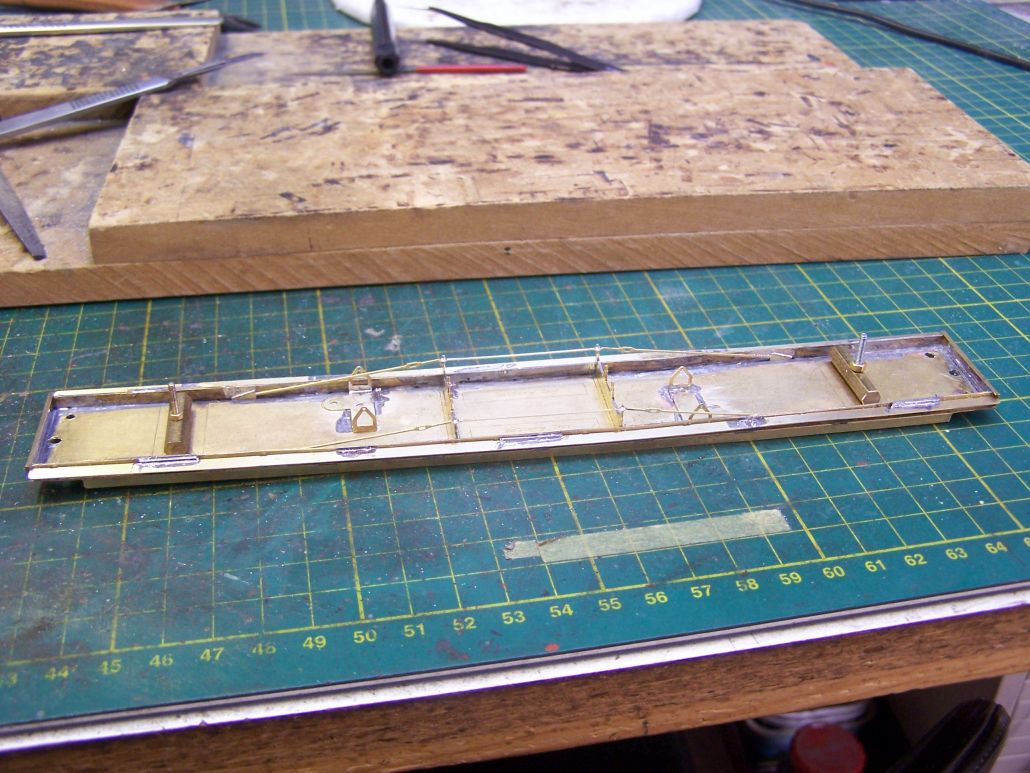
Steps attached, the trussing the brake gear supports are fitted and the high temperature soldering on the underframe is now done.
Until I remember something I've missed.
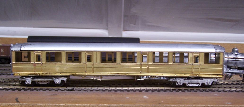
It's starting to come together and look like a Gresley vehicle, which is pleasing. You can see here how the centre roof section ends have been shaped to match the ends more closely.

I have heard that Dart are looking at a different approach to the Gresley roof. It is a fact that despite much filing and bending, it is not possible to get the end dome casting to sit with the cornice at anything but a jaunty angle. Once the aluminium centre section is in place there'll be more filing and filling to straighten the whole affair.

Once the two end domes are fixed the roof can be measured and cut. Cut slightly overlength and file down to a very snug fit, that'll save you some filling and sanding later. I managed to cut at a slight angle so I will have some work to do there. You can also see the step down from the aluminium to the cast end. Dress this down with a file while the roof is not yet attached, this will also save filling and sanding work later.

Back to the underframe next and a method I've adopted since I started building coaches for exhibition use. Underframe steps can be very vulnerable to bending or breaking off with handling, so I put lengths of .7mm wire underneath the step to give more surface to solder to. This is done by drilling a .75 hole just above the solebar flange, putting a bent length of .7mm wire through it as above, then soldering in place. The tail can be snipped off and dressed back so it doesn' t interfere with the trussing. For a full length step I use one at each end and one in the middle. I've been doing this for some time and no-one has ever commented on it as it's all but ivisible on the finished vehicle. I did have a slight pause as I was looking at photographs of D7s and the first one I found had individual steps under each compartment door. I think that may have been a wartimne economy measure, though, as thankfully all the others had a continuous step as here.

Steps attached, the trussing the brake gear supports are fitted and the high temperature soldering on the underframe is now done.
Until I remember something I've missed.

It's starting to come together and look like a Gresley vehicle, which is pleasing. You can see here how the centre roof section ends have been shaped to match the ends more closely.
- Dave
- LNER A4 4-6-2 'Streak'
- Posts: 1731
- Joined: Sat Nov 13, 2010 9:33 pm
- Location: Centre of the known universe York
Re: West End Workbench
The model is coming on very well, We forgot to look at it last weekend, and the 3 links........never mind.
Keep up the good work.
Keep up the good work.
-
jwealleans
- LNER A4 4-6-2 'Streak'
- Posts: 4276
- Joined: Wed Oct 25, 2006 8:46 am
Re: West End Workbench
I did say 'until I remember something I've missed' on the underframe and I had. There's a very prominent vacuum pipe which runs along the solebar on a Gresley carriage. Which side it goes seems to be something of a lottery, but on all the pictures of CKs I have where it was visible it was on the corridor side, so there it has gone. I use 0.9mm wire for this. The bends towards the end are quite distinctive, but I have to remember not to take it too far round the ends to the centreline of the carriage as it interferes with the coupling.
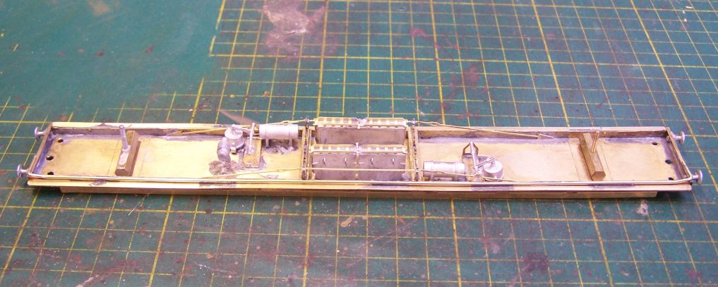
Once that was on the rest is lowmelt work and just the bog standard MJT components, for which the underframe is helpfully marked. The only little variation I add are the two wires from the dynamo which are probably invisible at normal viewing distance but do give it an additional fixing. The base always seems very small for the casting (though I can't ever remember one falling off). Also, apologies to any purists but I only ever fit the outside trusses. The inside ones are not visible and often interfere with the bogies so they're omitted. Having taken the picture I noticed that I hadn't added the dynamo belt, which I've now done.
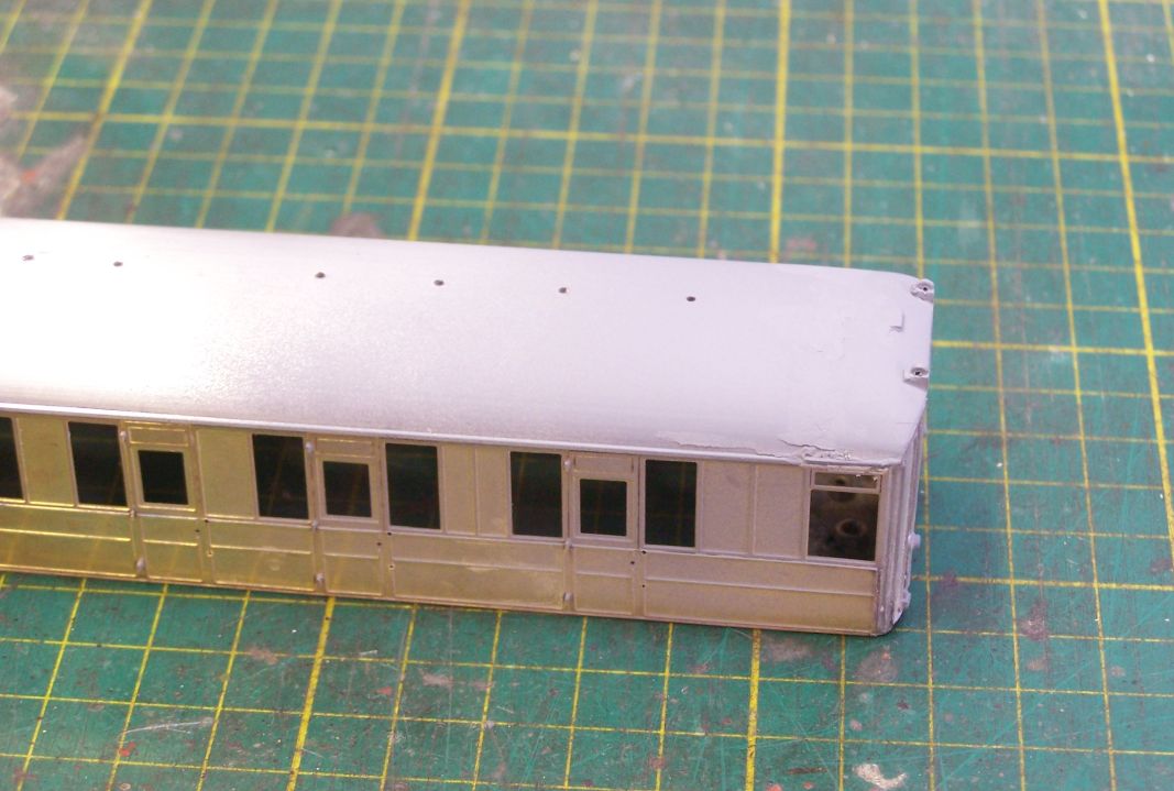
Roof secured with two part epoxy and then the joint filled, sanded, filled again and sanded again. I've put a light coat of primer onto it this evening which will help with what will ideally be the last round of filling and sanding tomorrow. I should say that before securing it I did mark and drill the vent holes. I dont' have a drawing for this vehicle, but helpfully the vents are in the centre of each of the compartment side windows, so once I had a couple marked as reference points it's easy to fill in the rest with a pair of dividers. For those who've never used one, there's a very helpful groove down the centreline of an MJT roof so you have a drilling guide. The water fillers and vent over the lav are on the joint or in the end casting so they'll be marked and drilled once the sanding is done.

Once that was on the rest is lowmelt work and just the bog standard MJT components, for which the underframe is helpfully marked. The only little variation I add are the two wires from the dynamo which are probably invisible at normal viewing distance but do give it an additional fixing. The base always seems very small for the casting (though I can't ever remember one falling off). Also, apologies to any purists but I only ever fit the outside trusses. The inside ones are not visible and often interfere with the bogies so they're omitted. Having taken the picture I noticed that I hadn't added the dynamo belt, which I've now done.

Roof secured with two part epoxy and then the joint filled, sanded, filled again and sanded again. I've put a light coat of primer onto it this evening which will help with what will ideally be the last round of filling and sanding tomorrow. I should say that before securing it I did mark and drill the vent holes. I dont' have a drawing for this vehicle, but helpfully the vents are in the centre of each of the compartment side windows, so once I had a couple marked as reference points it's easy to fill in the rest with a pair of dividers. For those who've never used one, there's a very helpful groove down the centreline of an MJT roof so you have a drilling guide. The water fillers and vent over the lav are on the joint or in the end casting so they'll be marked and drilled once the sanding is done.
-
jwealleans
- LNER A4 4-6-2 'Streak'
- Posts: 4276
- Joined: Wed Oct 25, 2006 8:46 am
Re: West End Workbench
Couple of days away from the bench on pond refurbishment duties. That's all done for the moment so once it started to cool down a little today we were back at it.
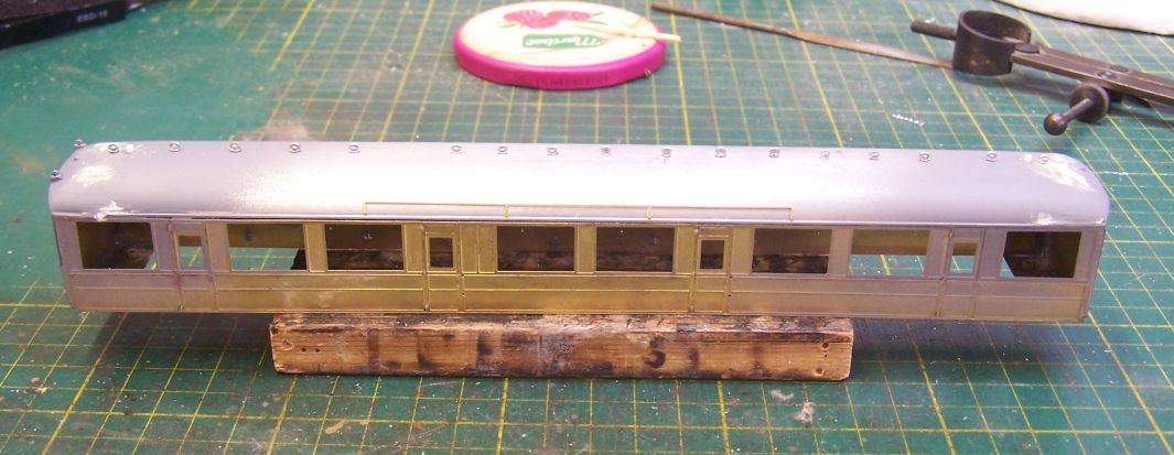
At the end of the last session I'd put some final smears of filer onto the ends and then added all the roof vents and destination board holders. A quick sand down today and the roof is as good as it's going to be. I should mention here that the roof paint I use has talc mixed into it so it does act as a filler for very small blemishes. I also filed along the cornice to make it as straight as possible and then added the door rain deflectors and raintsrips. The door rain deflectors are a very distinctive feature of these carriages, especially in teak livery. This one will be blood and custard so they won't be quite so prominent, but they will be there. They're made of 20 x 20 thou Evergreen strip with the ends cut to an angle. Water fillers, I should add are from 1.6mm plastic rod. The last feature to add will be the handrails either side of them.
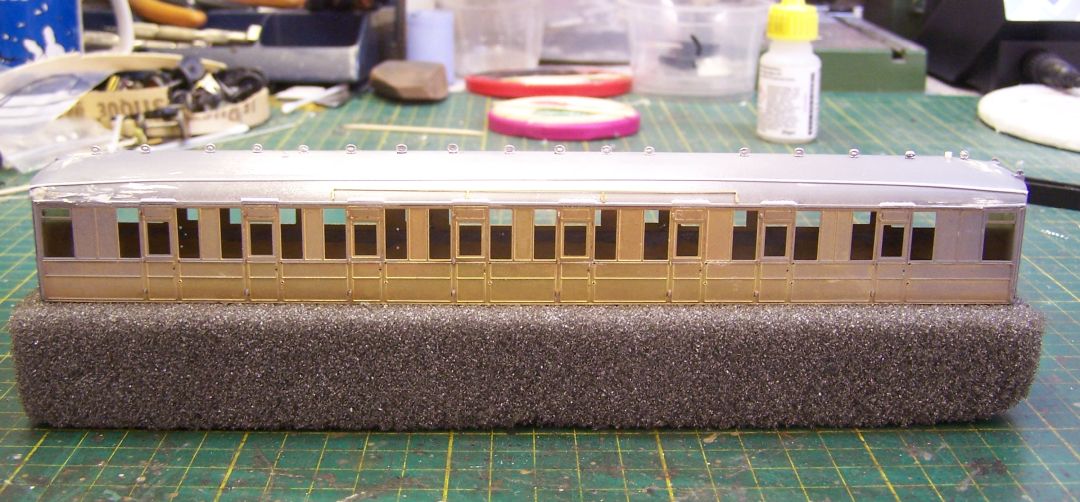
Rainstrip is 20 thou rod - once this has set I run a knife along the top to flatten it down a bit. Other than the roof handrails, the door vents are about the only thing remaining on the bodyshell. The floor and bogies have been primed and will be sprayed black - one upside of building a BR carriage, you don't have to mess about with teak solebars and wheel centres.

At the end of the last session I'd put some final smears of filer onto the ends and then added all the roof vents and destination board holders. A quick sand down today and the roof is as good as it's going to be. I should mention here that the roof paint I use has talc mixed into it so it does act as a filler for very small blemishes. I also filed along the cornice to make it as straight as possible and then added the door rain deflectors and raintsrips. The door rain deflectors are a very distinctive feature of these carriages, especially in teak livery. This one will be blood and custard so they won't be quite so prominent, but they will be there. They're made of 20 x 20 thou Evergreen strip with the ends cut to an angle. Water fillers, I should add are from 1.6mm plastic rod. The last feature to add will be the handrails either side of them.

Rainstrip is 20 thou rod - once this has set I run a knife along the top to flatten it down a bit. Other than the roof handrails, the door vents are about the only thing remaining on the bodyshell. The floor and bogies have been primed and will be sprayed black - one upside of building a BR carriage, you don't have to mess about with teak solebars and wheel centres.
-
jwealleans
- LNER A4 4-6-2 'Streak'
- Posts: 4276
- Joined: Wed Oct 25, 2006 8:46 am
Re: West End Workbench
Paint applied today in between other jobs. The body has had an all over coat of Halfords filler primer, inside and out, and then white along the sides.
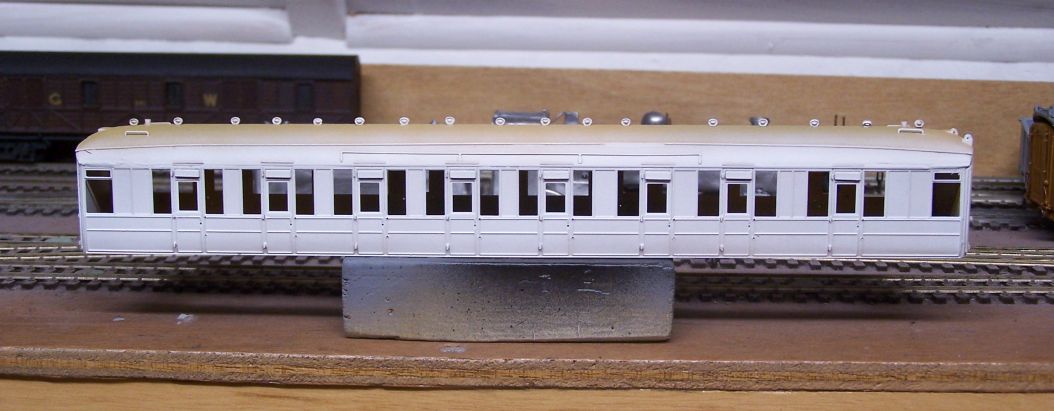
The inside coat is for the colour - it makes a good undercoat for the 62/186 I'll use there. The white is a good base for both the cream and crimson as they're both fairly transparent colours. It also makes any major blemishes obvious so I can try to do something about them before I start the topcoat application.
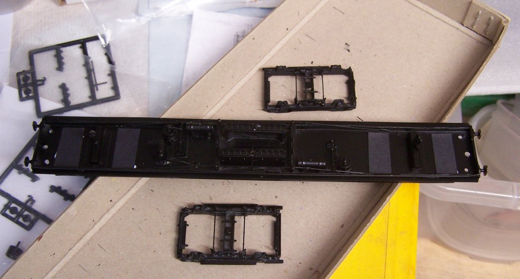
Floor and bogies now black. One fairly new change to my carriages is putting paper under the floor above the wheels so they won't short if they both touch the floor. This is a result of running on Dave Scott's DCC layout where the odd short is tolerated far less kindly than on most of the layouts I frequent. Although not many of my friends have adopted the Devil's Electrickery (and Wickham Market is very firmly DC), the possibility of visiting other DCC layouts remains. It doesn't do any harm to a DC layout to eliminate them either, of course. I had some black paper which was bought for corridor connectors but was too thick, so small pieces of that are attached with PVA.

The inside coat is for the colour - it makes a good undercoat for the 62/186 I'll use there. The white is a good base for both the cream and crimson as they're both fairly transparent colours. It also makes any major blemishes obvious so I can try to do something about them before I start the topcoat application.

Floor and bogies now black. One fairly new change to my carriages is putting paper under the floor above the wheels so they won't short if they both touch the floor. This is a result of running on Dave Scott's DCC layout where the odd short is tolerated far less kindly than on most of the layouts I frequent. Although not many of my friends have adopted the Devil's Electrickery (and Wickham Market is very firmly DC), the possibility of visiting other DCC layouts remains. It doesn't do any harm to a DC layout to eliminate them either, of course. I had some black paper which was bought for corridor connectors but was too thick, so small pieces of that are attached with PVA.
-
Hatfield Shed
- LNER A4 4-6-2 'Streak'
- Posts: 1722
- Joined: Fri Dec 23, 2011 3:34 pm
Re: West End Workbench
Very neat altogether, will look properly handsome.
For preference cut clearances in metal structure for flanges, tyres, other live moving elements such as rods and crankpins, if feasible.
Flanges in particular will cut their way through paint, plastic, paper, barriers.
Best resistance to being worn away, 24 hr Araldite. (If anyone knows of a better material for the purpose, do tell please.)
I have a little holding pen for items 'stopped for treatment', waiting on a mix of Araldite which has been made for some other purpose.
I should add that if the layout track was laid perfectly plane there would be no problem. But my layout design requires many transitions on and off gradients, with the consequence of bogie and truck mounted wheels rising regularly, relative to fixed structure.
On the prevention of shorts front, which is a very real issue for DCC operation of metal construction models, the sum of my 20 + years experience with DCC:jwealleans wrote: ↑Sun Jul 09, 2023 8:53 pm ...One fairly new change to my carriages is putting paper under the floor above the wheels so they won't short if they both touch the floor. This is a result of running on Dave Scott's DCC layout where the odd short is tolerated far less kindly than on most of the layouts I frequent...
For preference cut clearances in metal structure for flanges, tyres, other live moving elements such as rods and crankpins, if feasible.
Flanges in particular will cut their way through paint, plastic, paper, barriers.
Best resistance to being worn away, 24 hr Araldite. (If anyone knows of a better material for the purpose, do tell please.)
I have a little holding pen for items 'stopped for treatment', waiting on a mix of Araldite which has been made for some other purpose.
I should add that if the layout track was laid perfectly plane there would be no problem. But my layout design requires many transitions on and off gradients, with the consequence of bogie and truck mounted wheels rising regularly, relative to fixed structure.