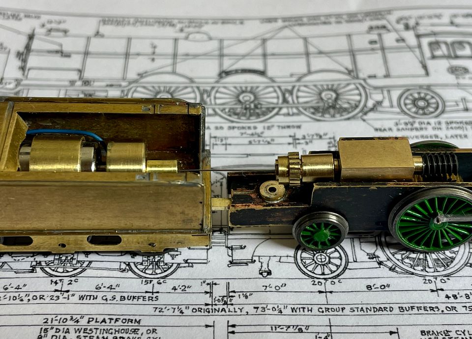
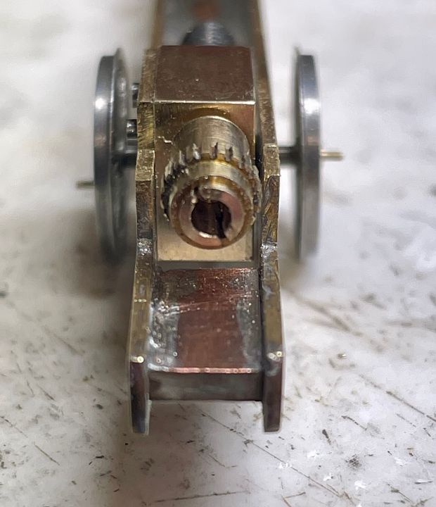
The gear head and loco universal joint were finished a few days ago; the worm shortened and thrust washers placed at each end.
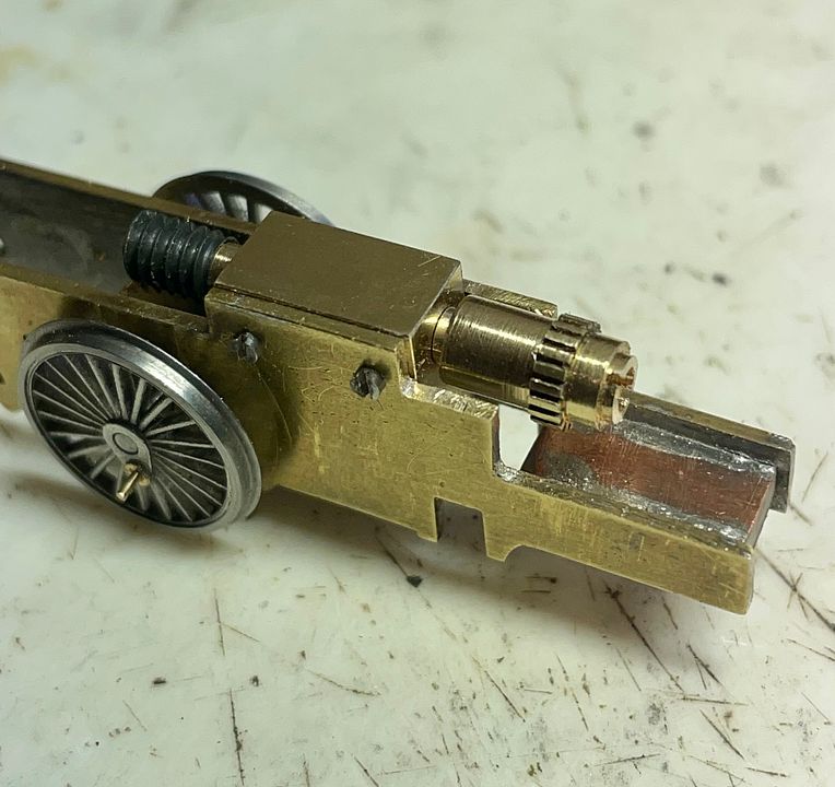
The cut down teeth on the UJ cover is from an old eccentric Association gear. It makes it easier to turn the shaft by hand.
The brake hangers on the frames were made from pivot steel soldered through holes into place with a very effective solder and flux.
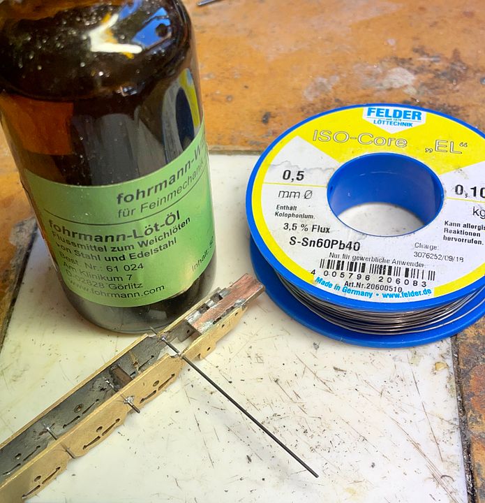
The flux is a very corrosive oil and so the chassis was degreased and then boiled in water for 5minutes.
The next stage was to complete the frame spacer at the front end of the loco; the notches inside the frames are to take the nuts of the studs that will hold the cylinders in place.
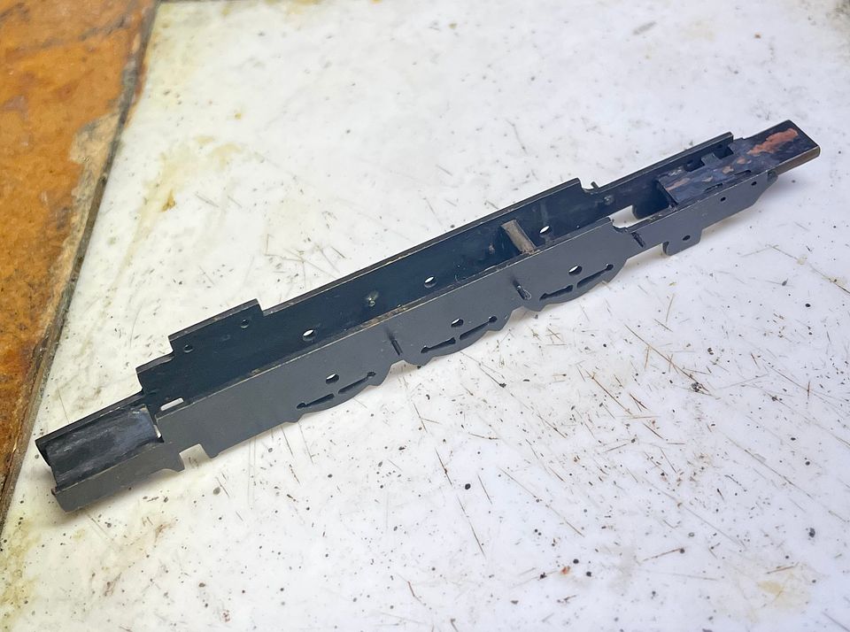
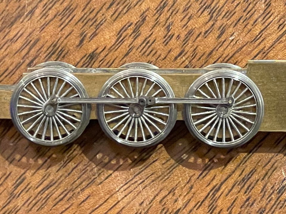
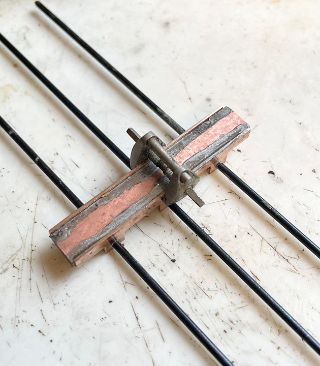
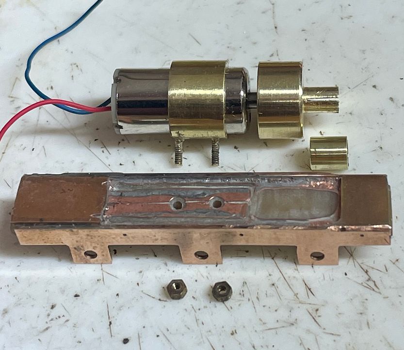
The frames were chemically blacked: much better than painting. The drive from the tender needed a chassis, so this was cut out of two layers of phosphor bronze strip sweated together.
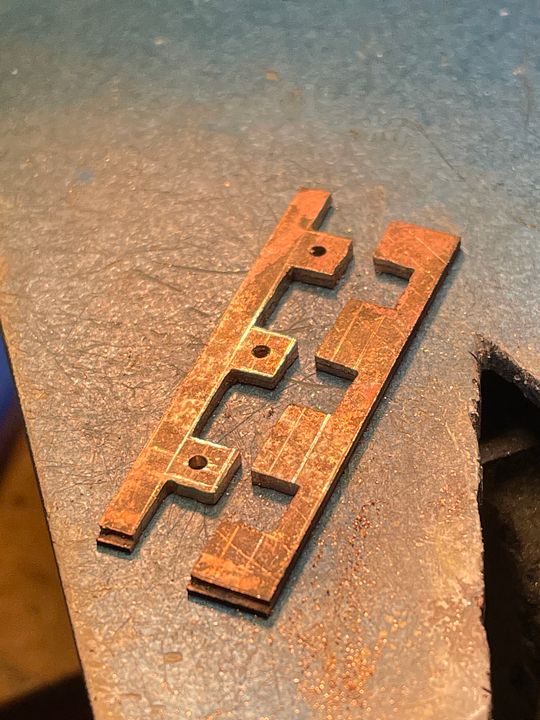
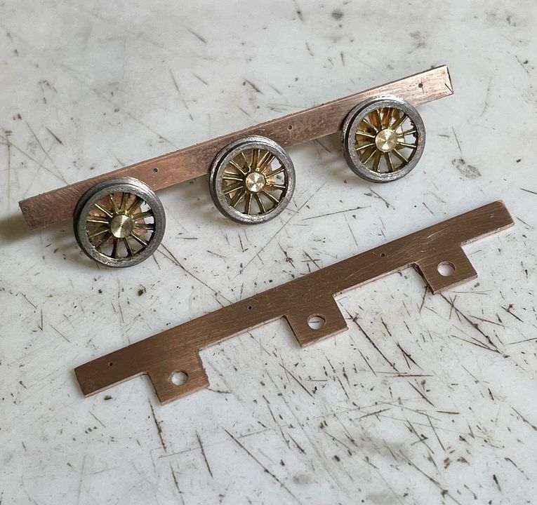
The frames were clamped up onto the PCB spacer, held in place by an orthodontic arch expander, and the siting rods (as usual) helped in alignment before soldering.
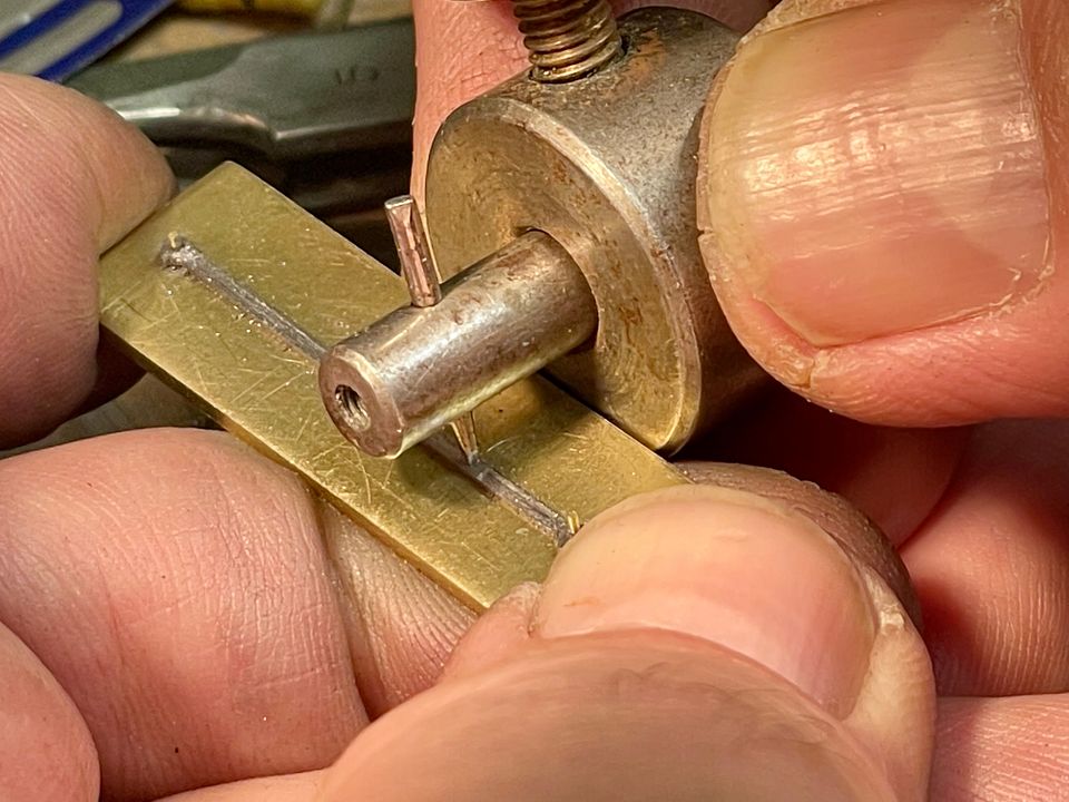
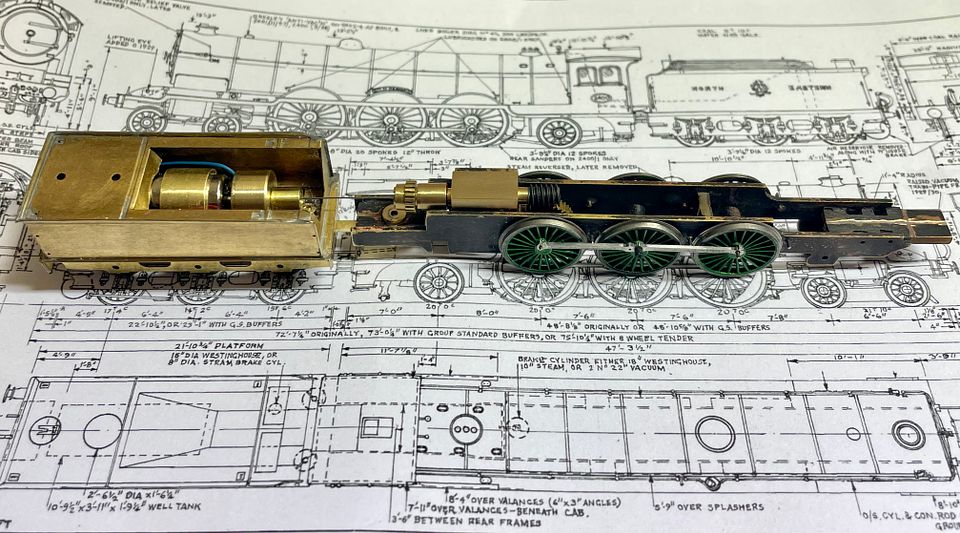
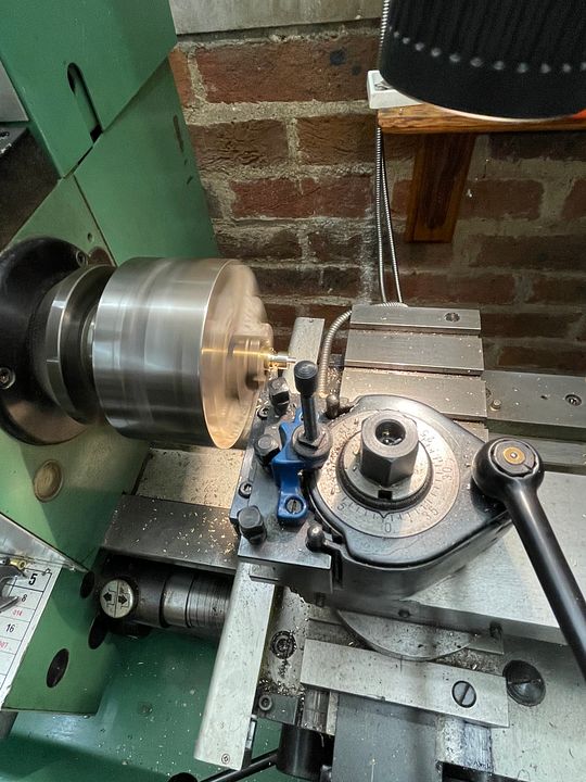
The Tram Fabrik motor obviously needed the other half of the UJ and so this was also incorporated into a flywheel. This was started on the big lathe in the garage: namely the main body, the smaller diameter UJ section and the 2mm diameter counter bore.
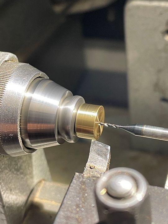
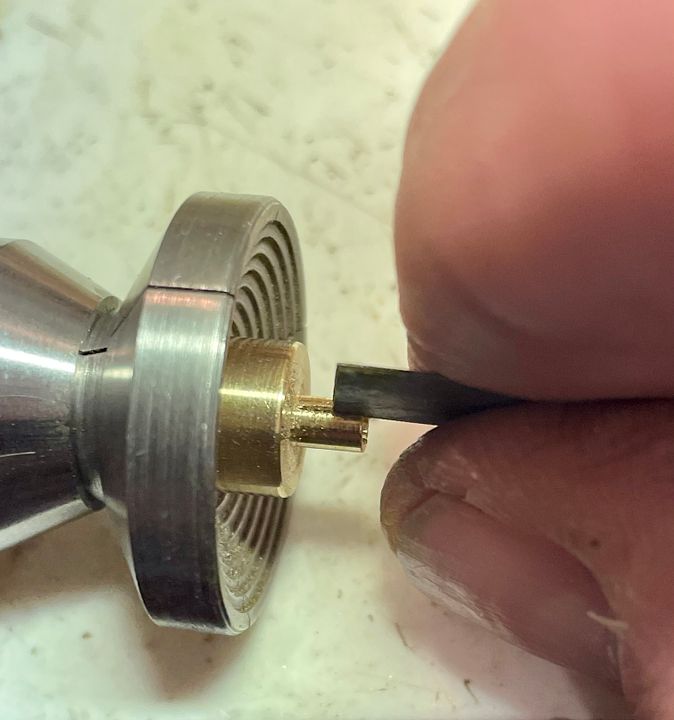
It was then taken into the garret workshop and finished off by drilling the shaft hole (0.9mm with a short section at 1.0mm) mounting the UJ section in a collet in the watchmakers lathe (it’s also much warmer upstairs)
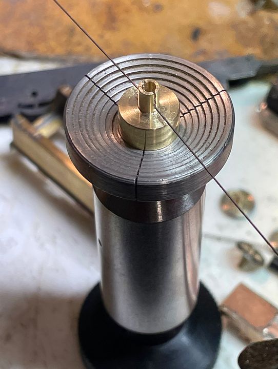
The hole was then taken up in size with a tapered broach until it just slipped onto the motor shaft to within a millimetre of the final position. The UJ slot was cut with a piercing saw and then finished with a slitting file, whilst holding it in a mandrel and a stepped chuck.
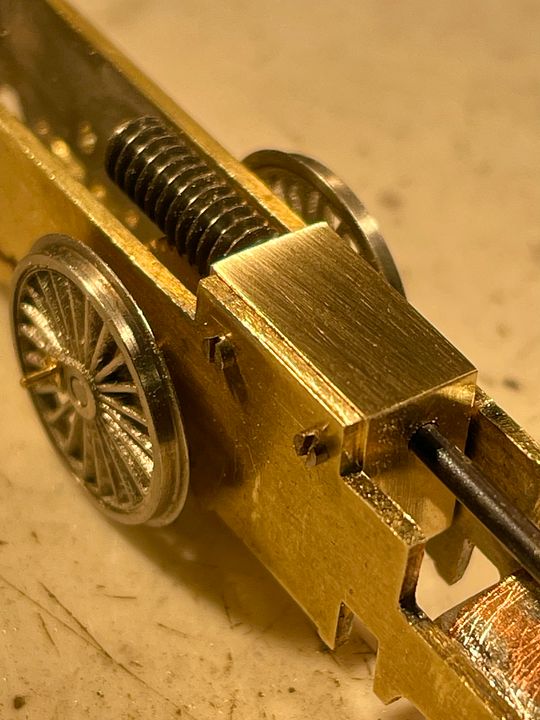
The motor itself is mounted in a brass collar with two 14BA studs silver soldered to it. These are then bolted through the PCB spacer.
The flywheel was gently pushed home with some Loctite 601 on the shaft. The whole assembly easily fits into the tender: it could have had a bigger flywheel, but that would have sat quite a long way forwards and not too good as a side load on the front bearing.
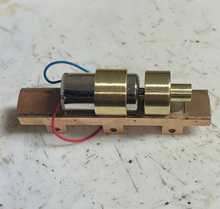
The two PCB pads at each end of the tender frames are Araldited in place and slightly raised to keep the body from shorting out the split chassis.
Anyone who has got this far deserves a medal!
Tim