Thanks Paul, I have sent you an email on the subject of the instructions.
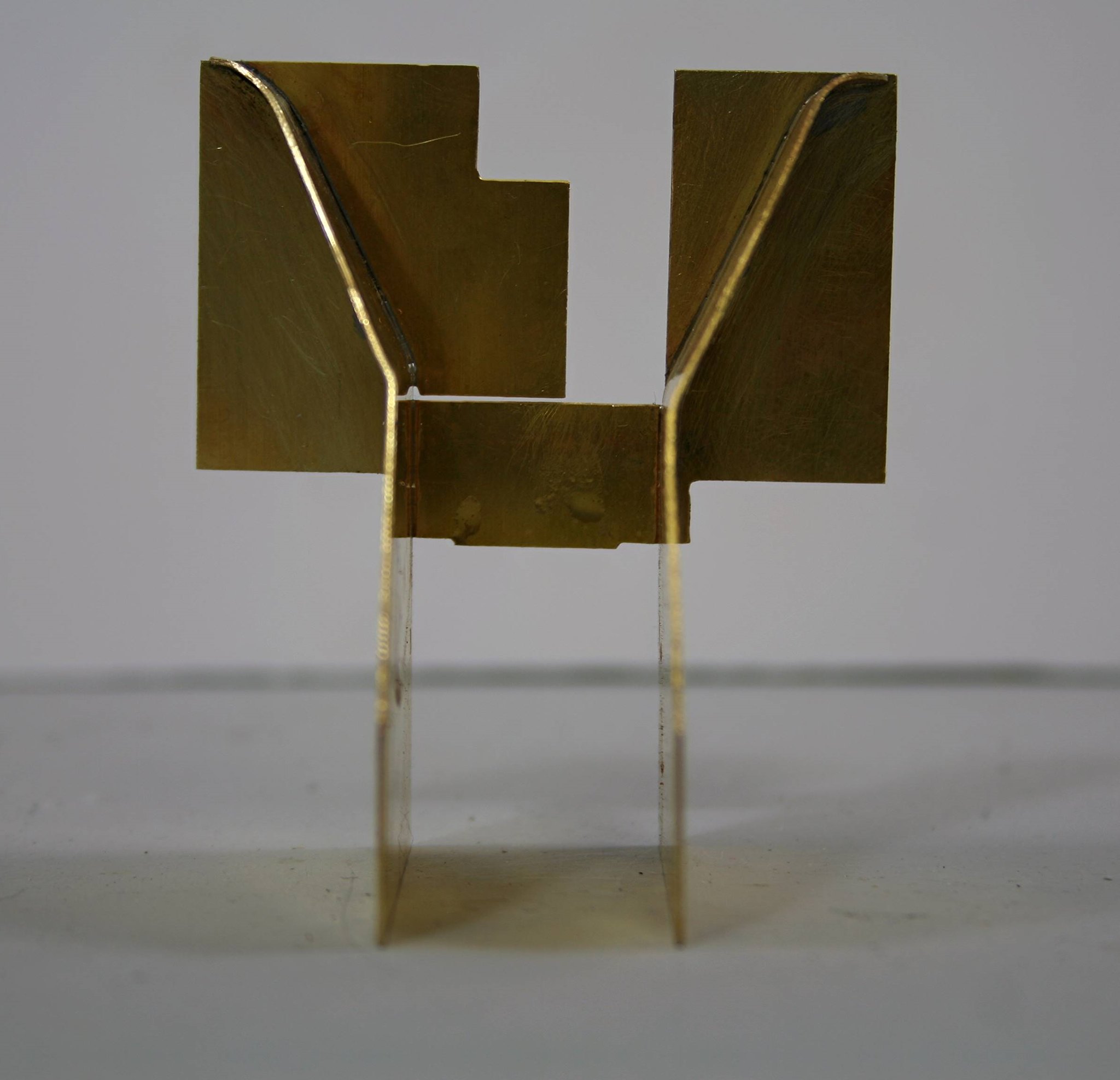
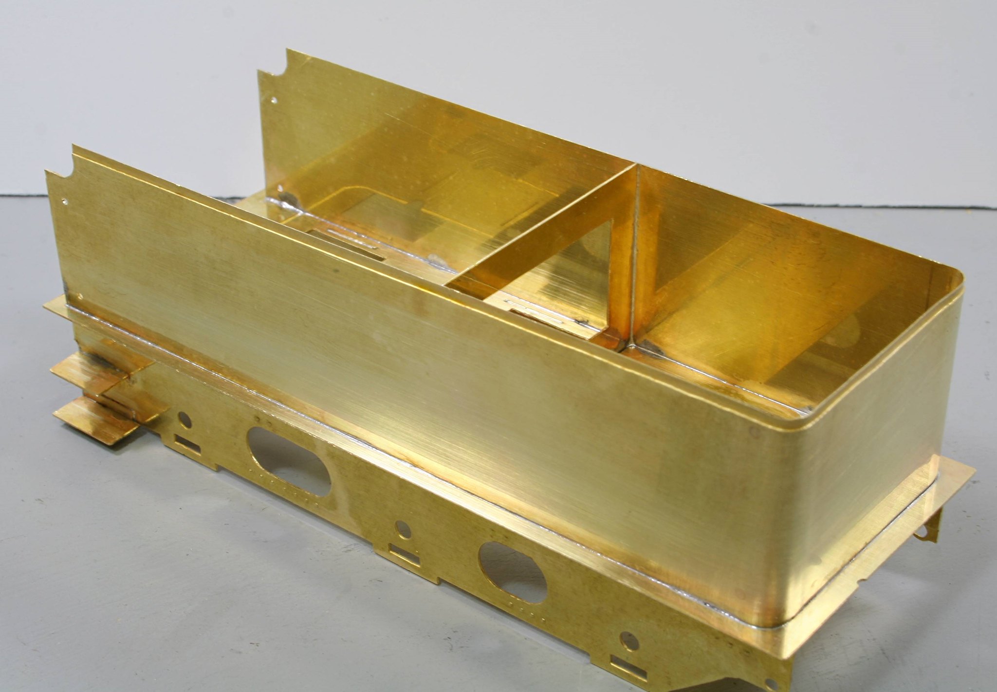
Further work on the tender last night got one of the more difficult bits behind me - bending the one-piece tank sides/end.
However, I will start off with a bit of a gotcha! The instructions tell you if modelling post 1940 to drill out two etched dimples on the rear right hand side of the tender for hand rails that must have been fitted to some tenders at some point.
Having done it I immediately started to think I wonder. Sure, enough when I looked at photos of 64206 which is the loco being modelled I noted no rear handrail....
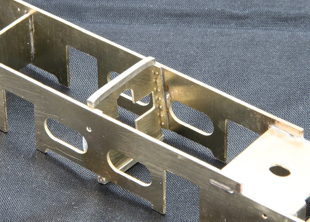
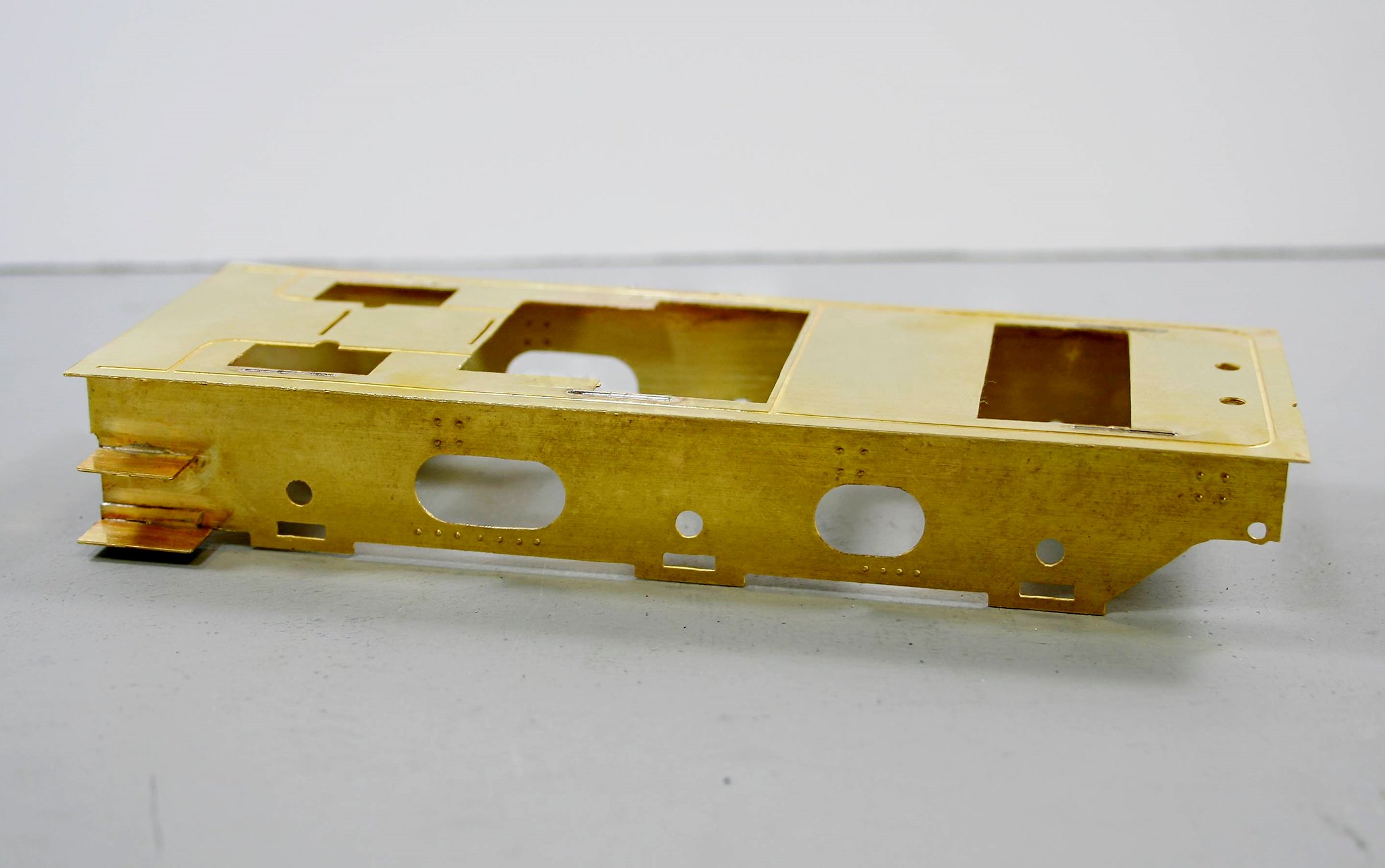
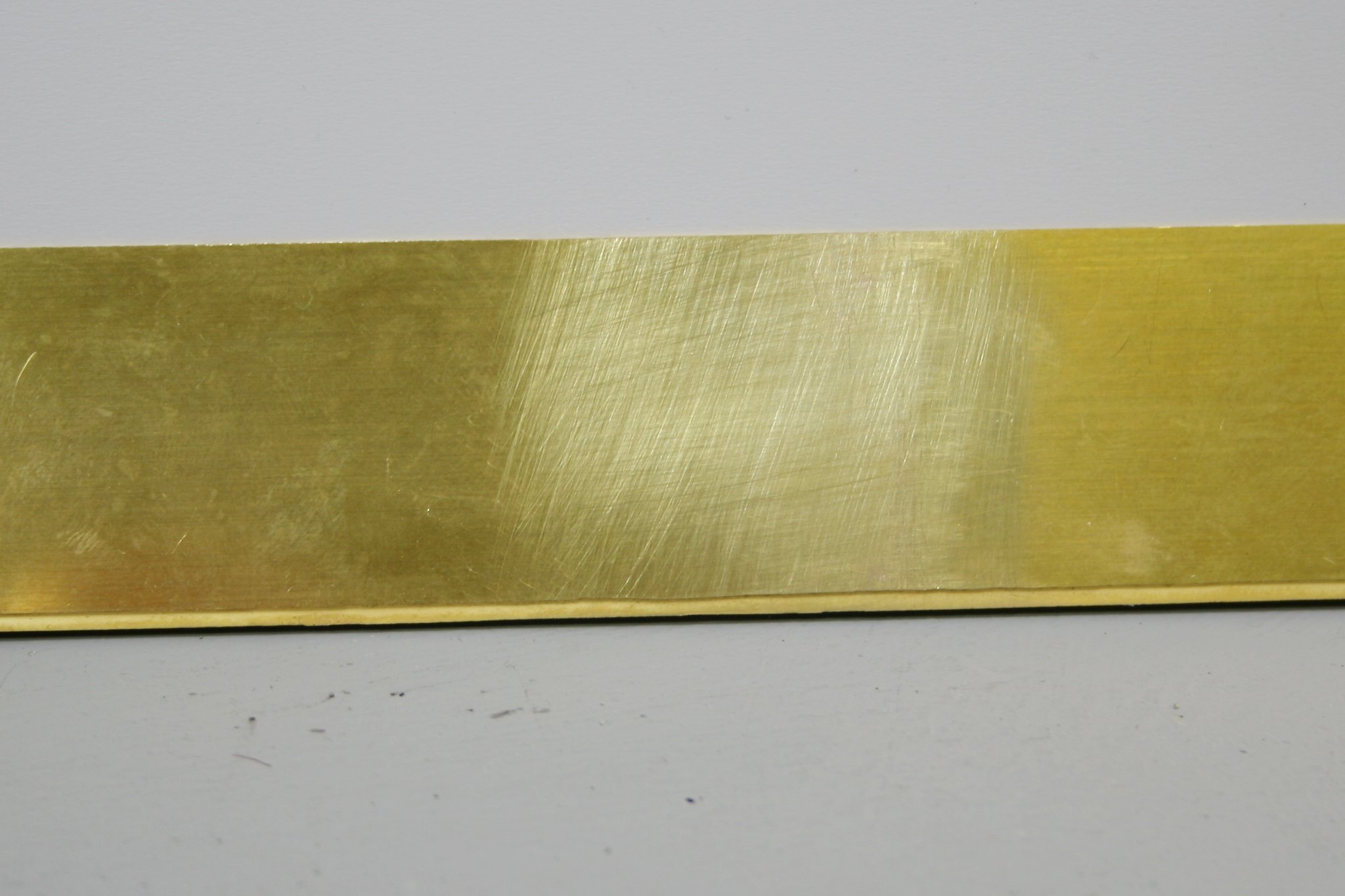
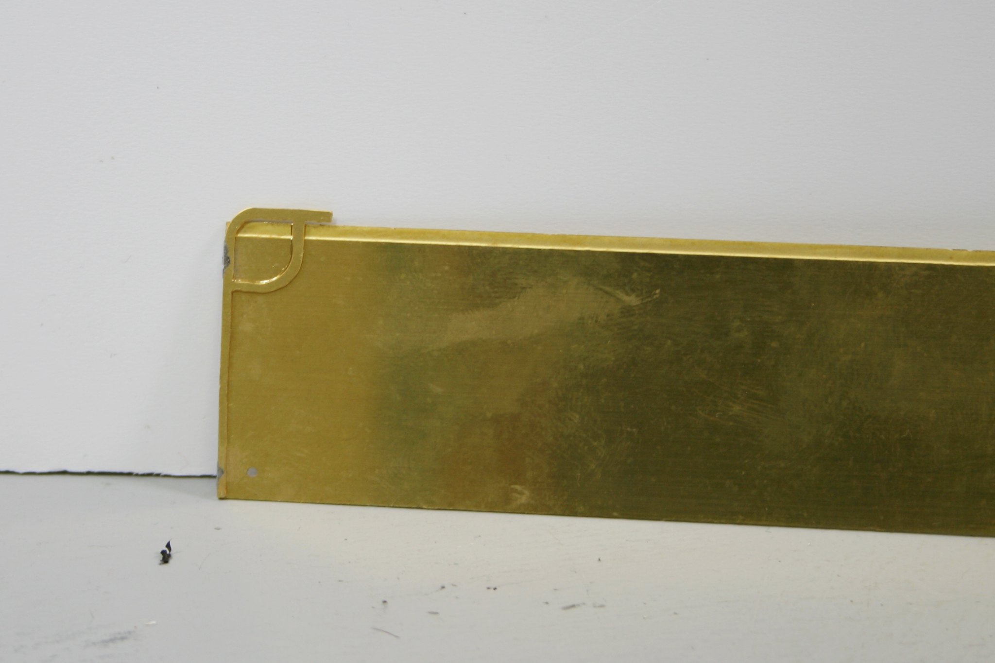
So, I opened out the holes to 1.55mm and soldered some stubs of rod in - this is it from the inside
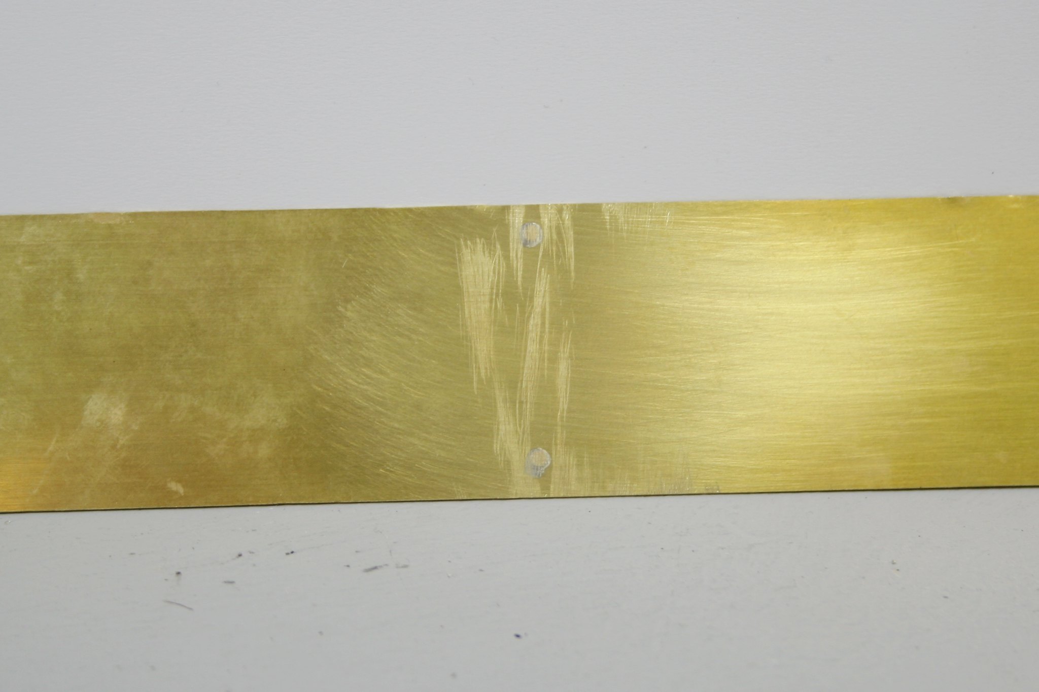
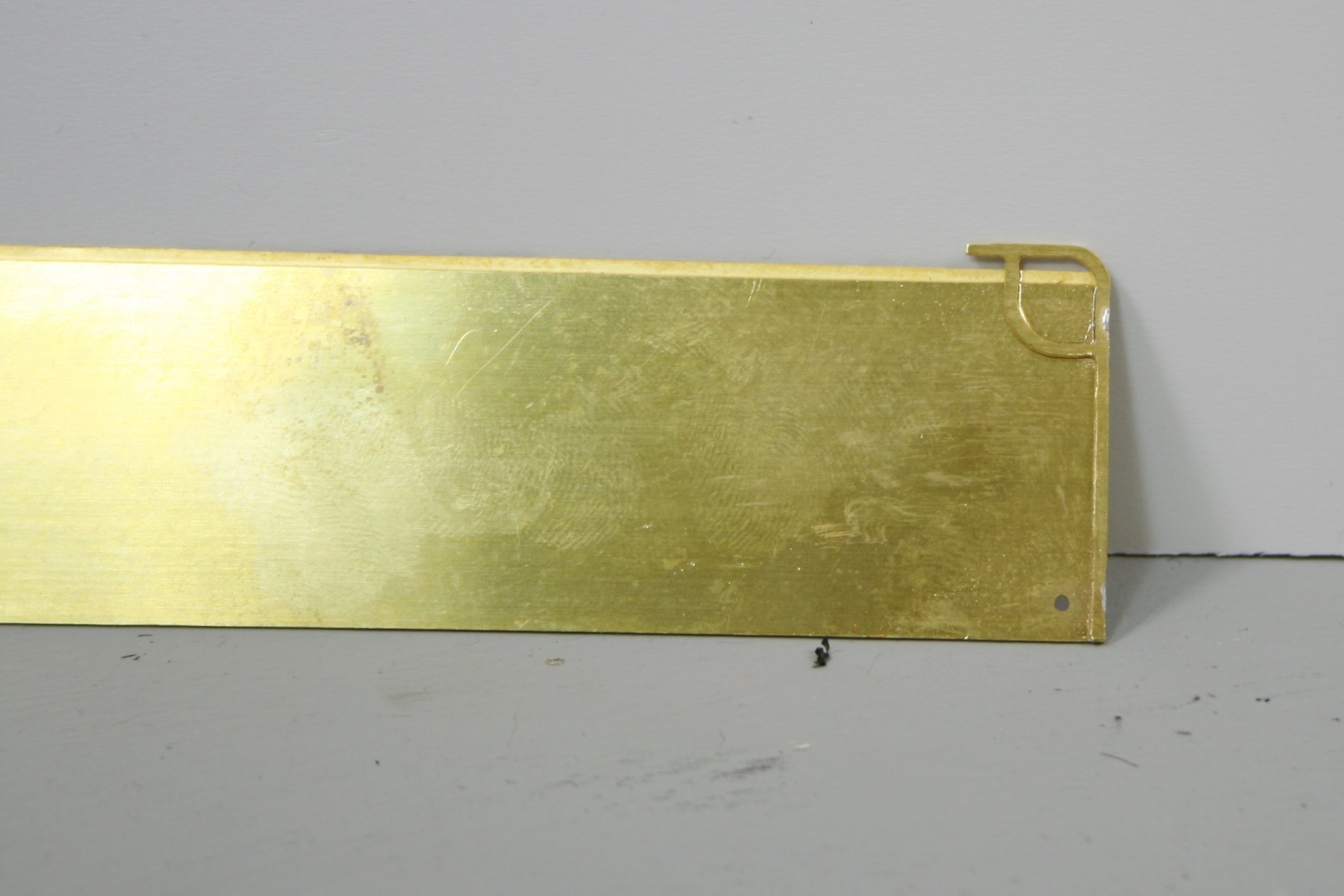
And from the outside - thankfully nothing shows
Next the tender sides are rectangular but on the real thing on the tender that I am working on there are cut outs for a handrail as in this example by Ron Bowyer.
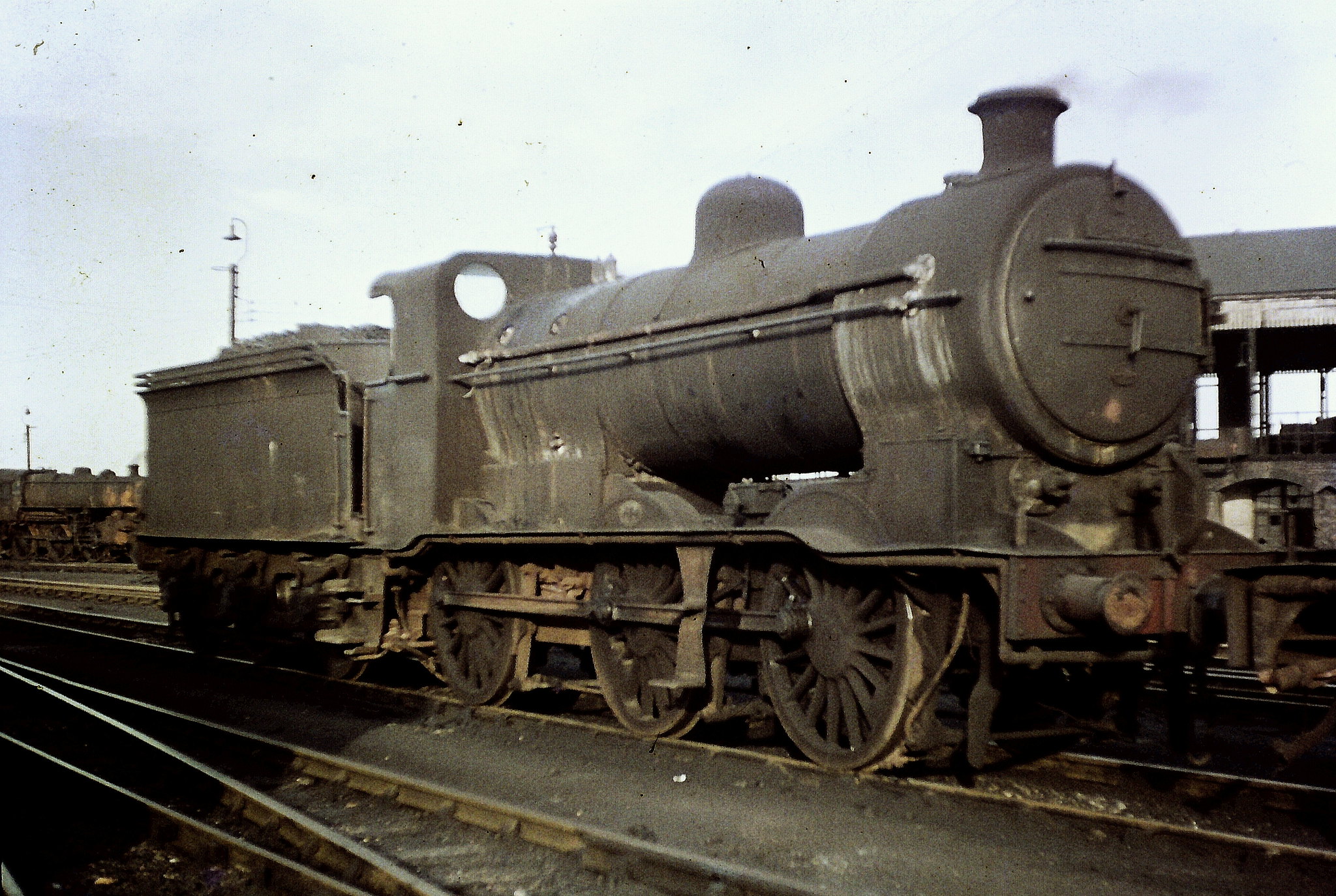 GNR/LNER Gresley "J6" class 0-6-0 No. 64223.
 by
Ron Bowyer, on Flickr
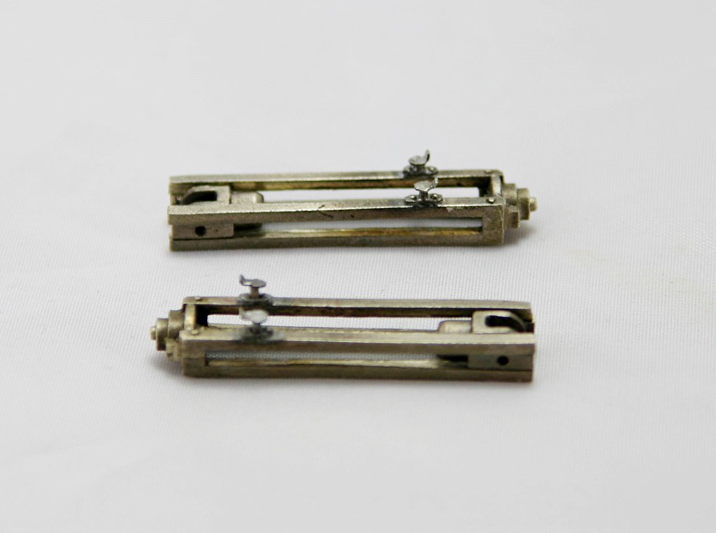
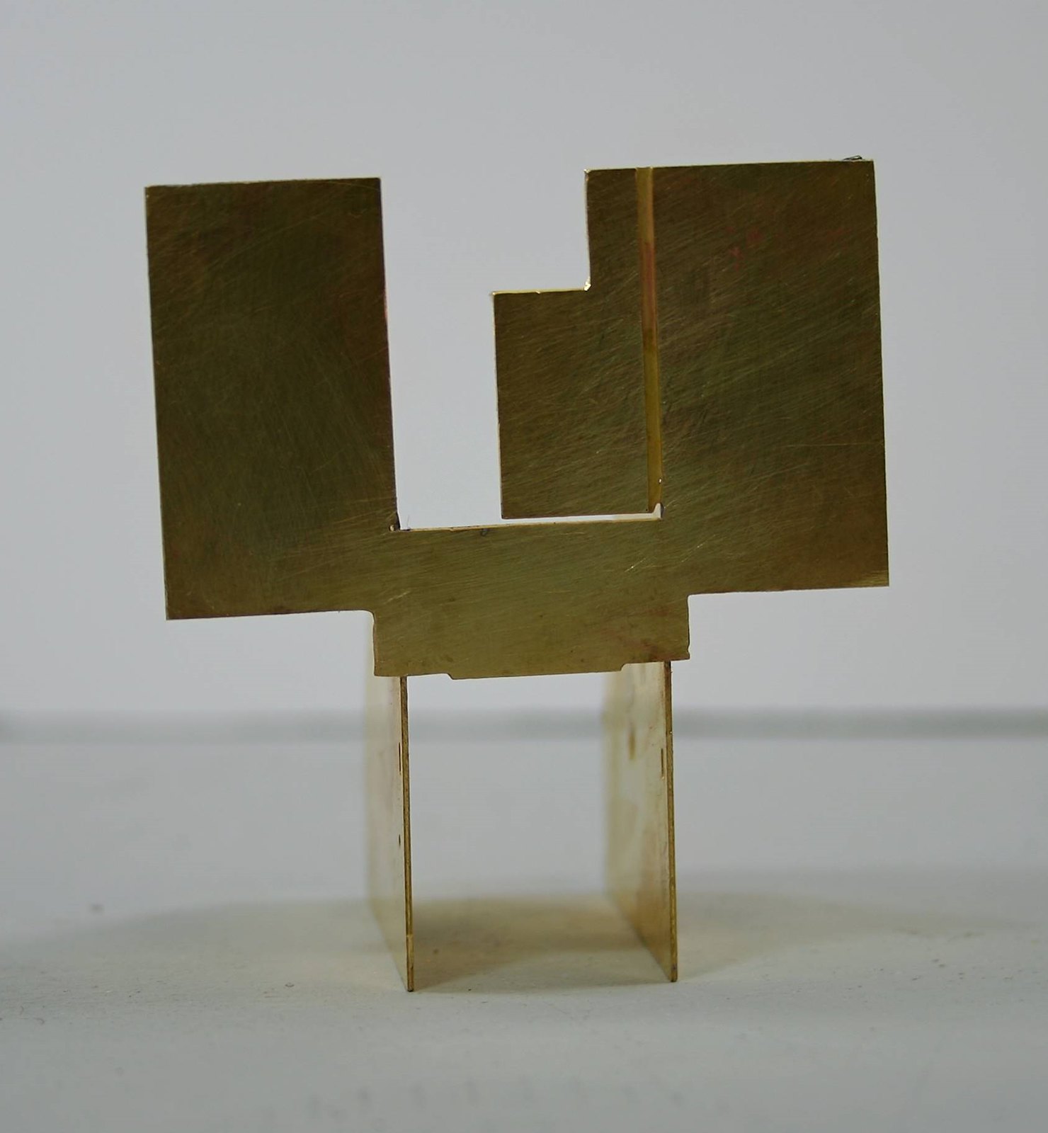
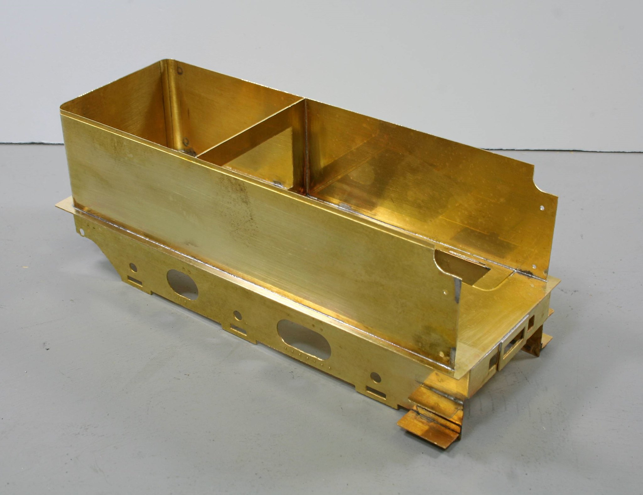
I have to confess to struggling with the instructions on this point so I went my own way. There are sections of etched beading to represent this and having worked out for myself how I believe they are meant to fit I tacked them to each end
This allowed me to scribe a line to cut/file to and then I unsoldered them and removed the bits that needed removing. Time will tell as to whether what I have done is correct but studying various photos it looks right.
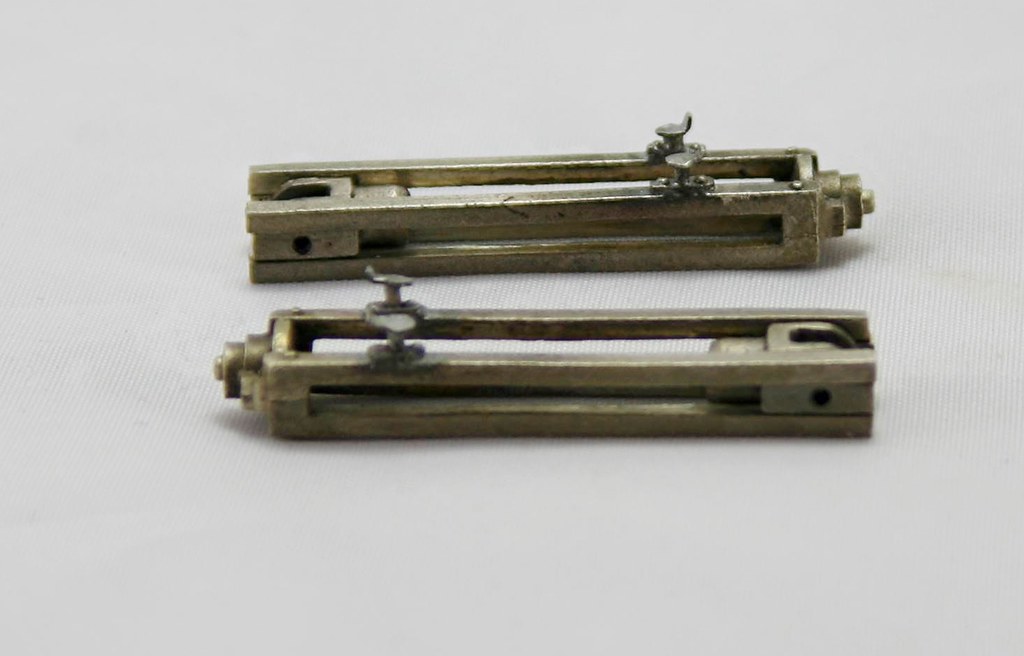
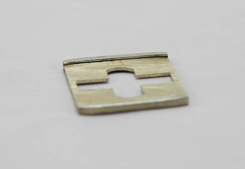
The next job was to drill out one of two dimples for the front handrail knob - these are design for a short rail where the top is cut out as I have done or a long rail where the side is left at full height. I drilled out the lower ones.
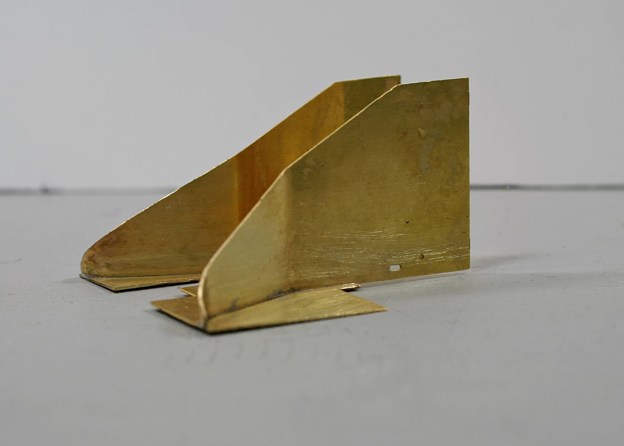
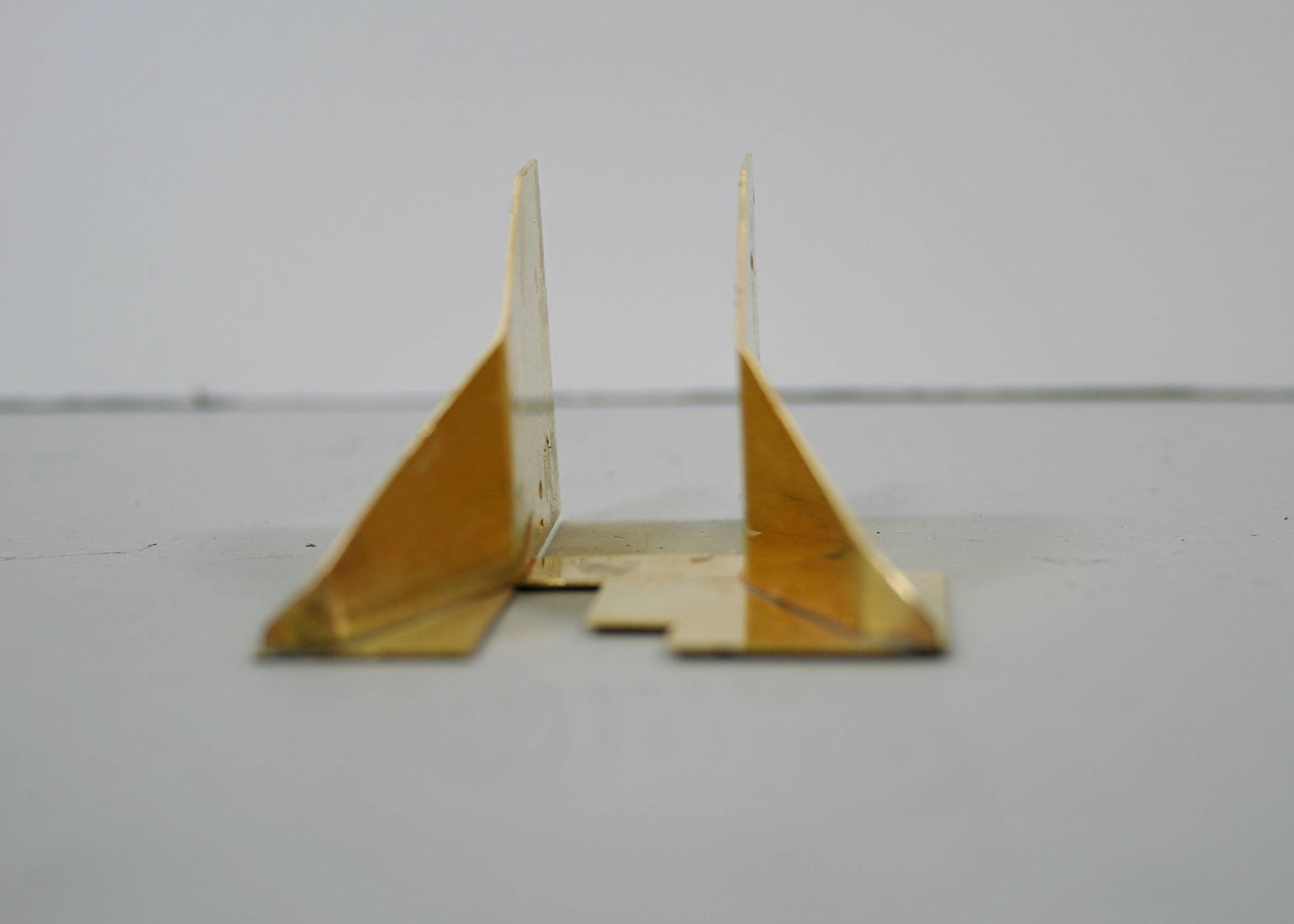
Then I carefully marked out where the first bend should be and then bent it using my Metalsmith Drilling table with a rod slightly smaller than the required bend clamped to it.
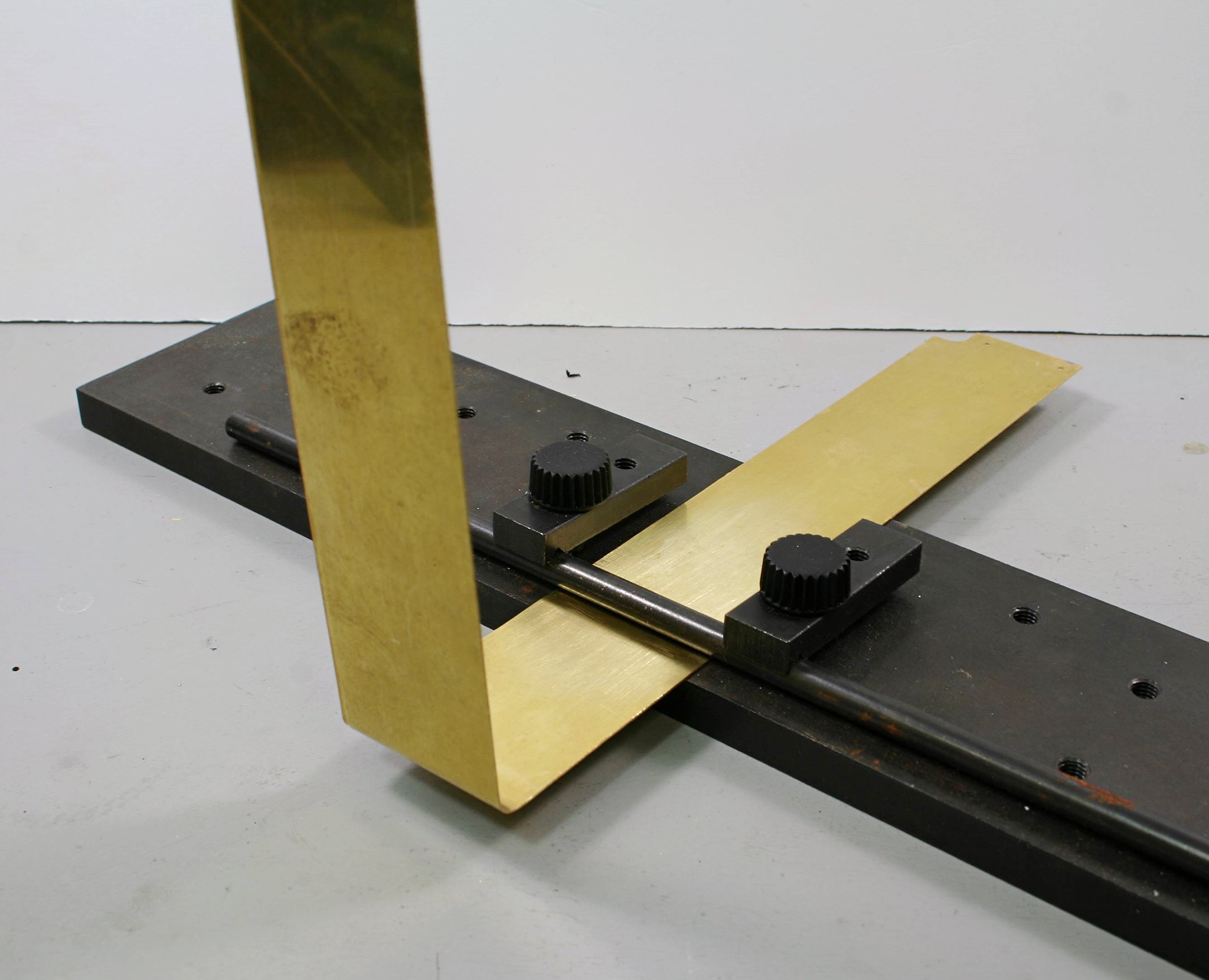
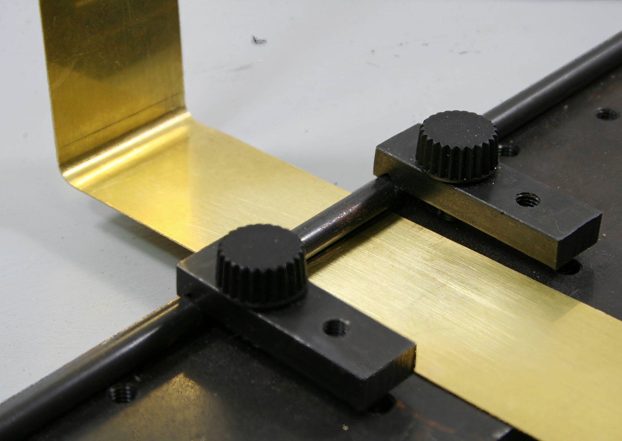
If this sort of thing scares you take heart. I didn't get it right first time, I just calmly straightened it with fingers and thumbs finally using smooth bladed pliers to finish off and them remeasured and tried again. The first side (the one in the photos) I got right on the second attempt. The other side took three goes.... but I got there.
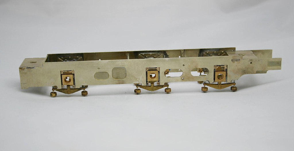
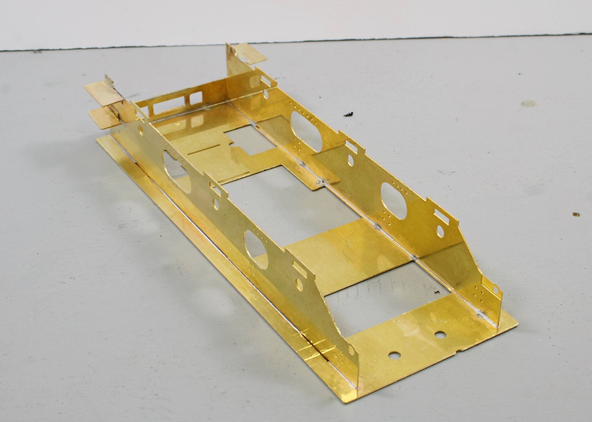
Next up is to solder in the bulkhead.
Where the instructions are really lacking is that they refer to parts but don't number them so you are constantly searching the scans of the etches and the index to find out which part you are looking for - the scans are labelled with part numbers and there is an index but it would be so much better if the instructions had part numbers alongside the text.
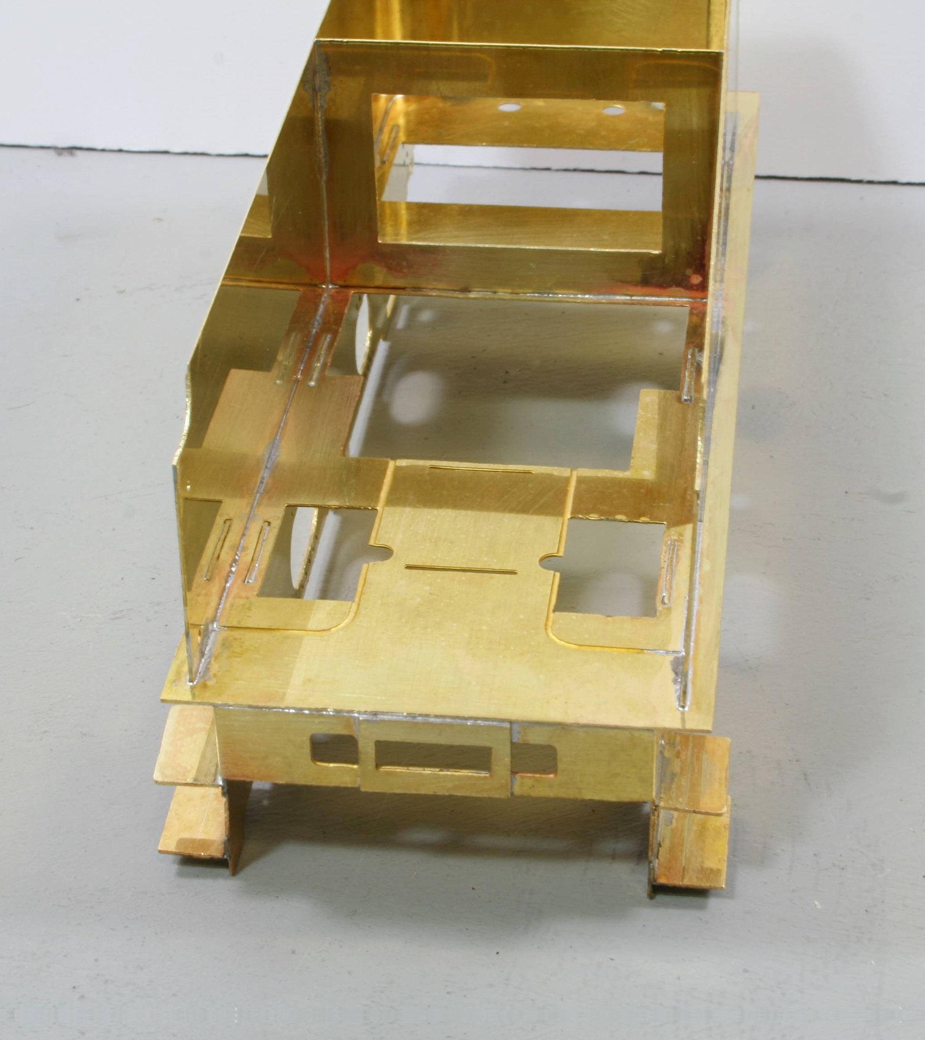
Then lastly solder the side/end piece to the footplate.

 [/url]
 [/url]
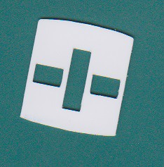
 am[/url], on Flickr