Page 14 of 15
Re: Gladiator LNER/BR J6 - Inside Motion Now Working
Posted: Mon Jun 27, 2022 9:53 am
by Robpulham
A couple of weekends ago I was demonstrating Loco building at the Stainmore Railway Model Railway show. I took along the chassis for the J6 and had it running on the rolling road all weekend. Besides giving the motion a really good bed in it attracted a lot of attention.
So much so that I plan to make up another chassis with inside motion for my demo stand.
On the back of a great weekend out I decided to see if I could crack the construction elements of the J6 last week.
The remaining jobs were.
Fit glazing
Add Milliput to the back of the balance weights to make them solid rather than just an etched front.
Fit the sand pipes
Fit the remaining linkages between the brake pull rods and the brake cylinders
Fit some Frame extensions under the boiler between the front pairs of wheels to hide the rear of the wheels – following Tony Geary’s lead.

Balance weights, I added a coat of primer to bled it all in before final paint and weathering.
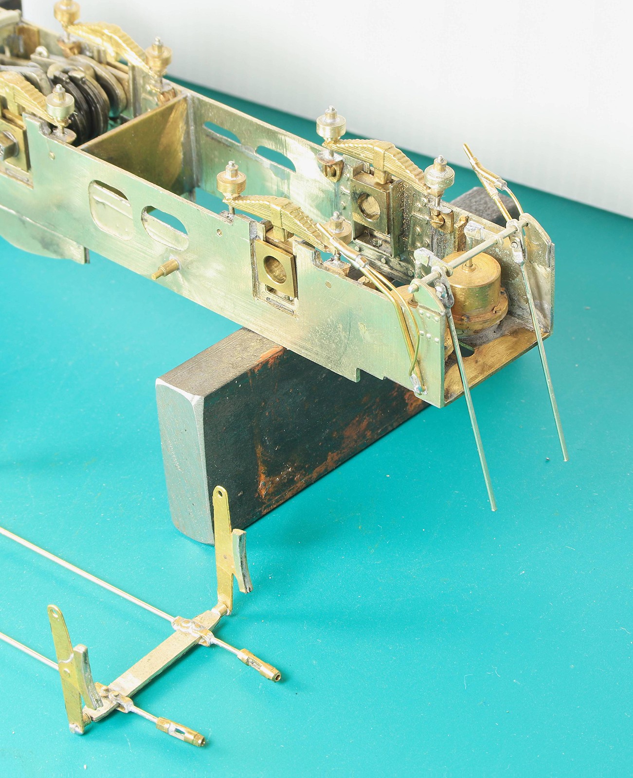
The first bit of the brake linkages

Front sandpipes and Frame extensions. Before fully soldering them in I tested the frame extensions at one side by tacking them in and the seemed perfect. But the chassis mustn’t have sat down properly because I noted while testing for clearance on the rear sandpipes that they need trimming down a bit.

Rear sandpipes. I had to fit the tops of them very close to the frames to avoid the injector pipework but I got there after two or three adjustments.


Last but not least a couple of shot of the remaining brake linkages. Although soldered at the rear the ends of the rods are a loose fit in the turnbuckles so allowing removal of the brakes.
Re: Gladiator LNER/BR J6 - Inside Motion Now Working
Posted: Sat Jul 02, 2022 10:23 pm
by Robpulham
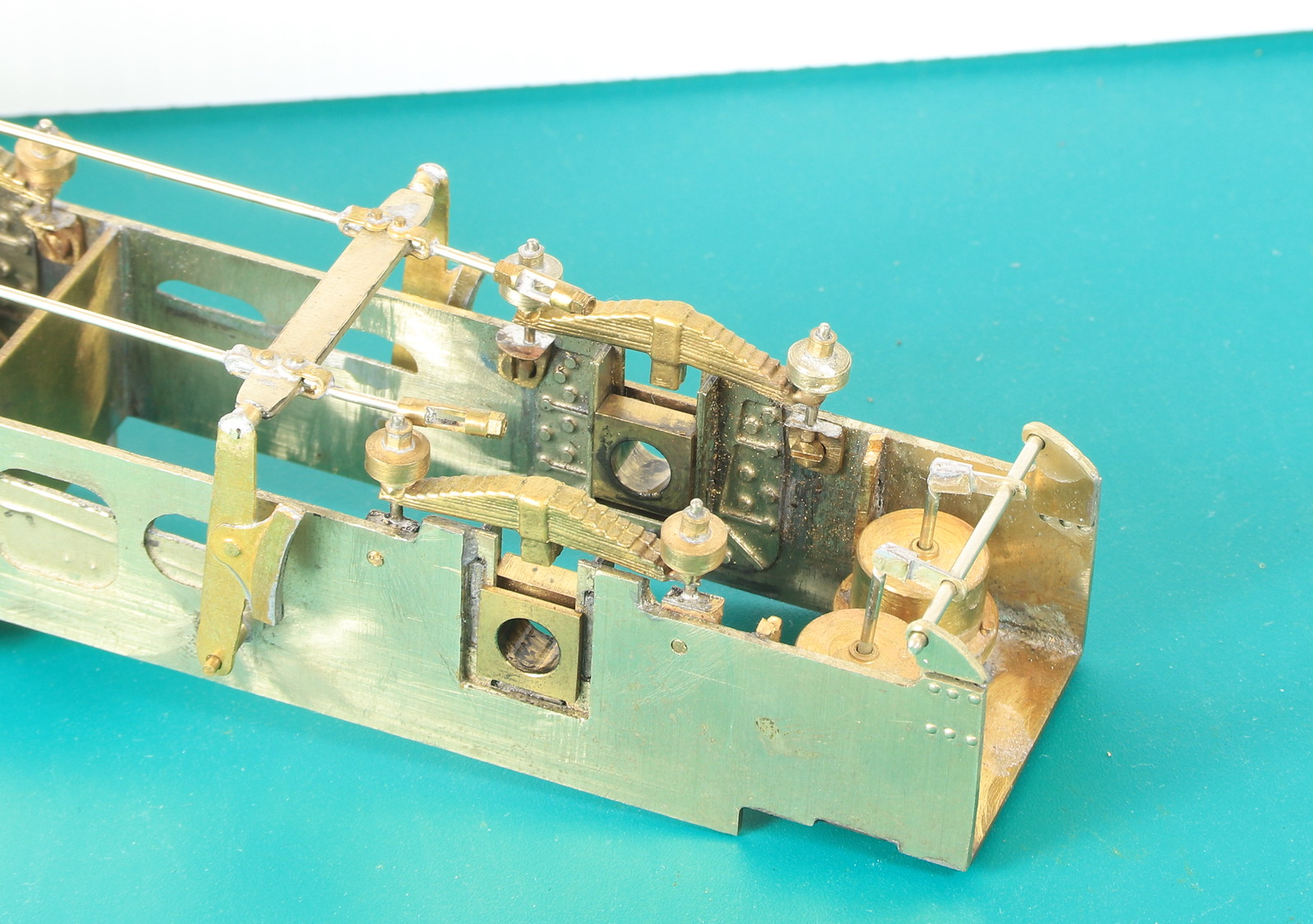
Paul Craig asked if I would show some detail of how the brakes fitted just after my last post but it took until today to get around to doing it.
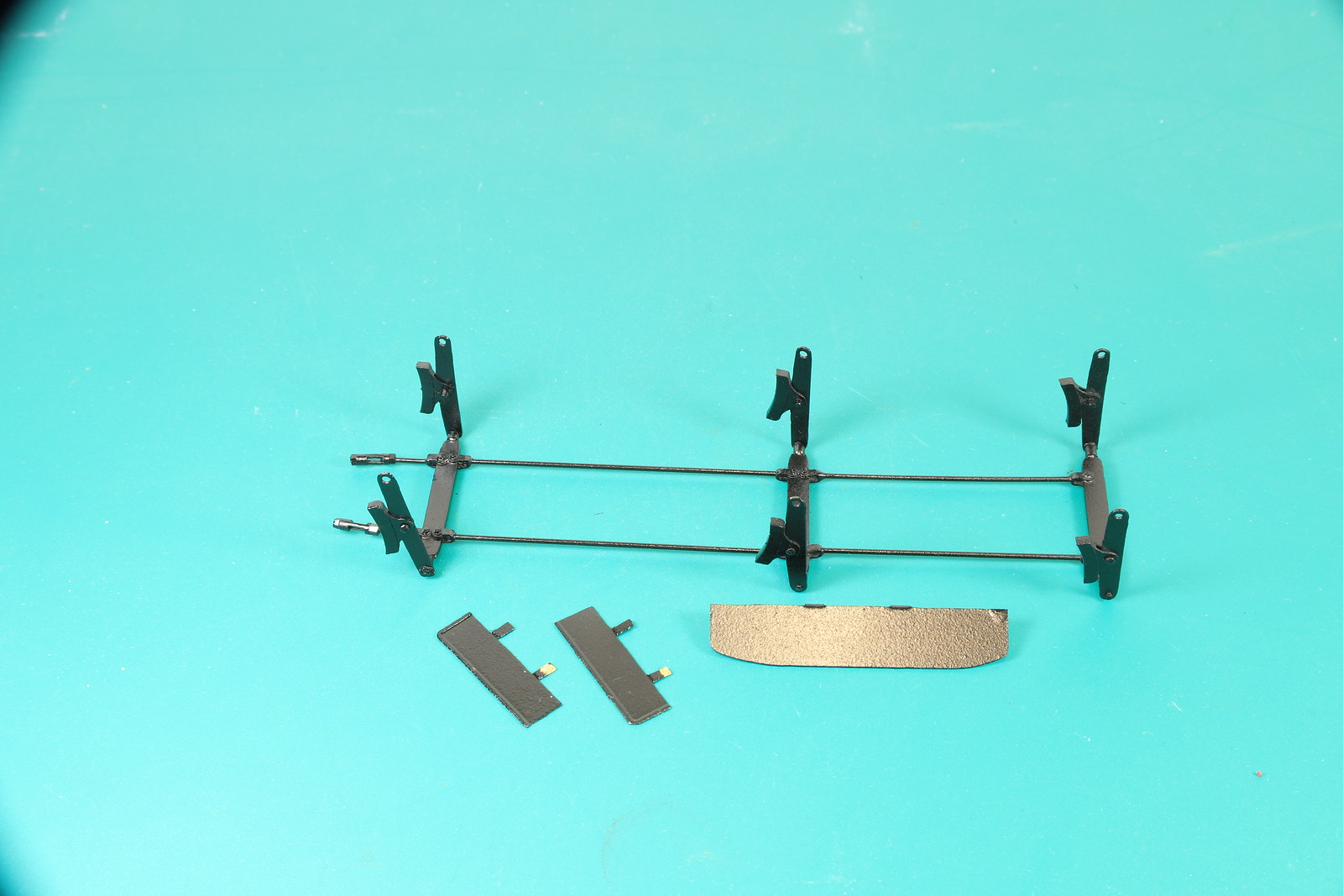
The brake hangers clip over the ends of the pivot pins which are in effect small pegs.
The brakes hangers are all soldered to the crossbeams and the pull rods are soldered at a fixed distance between them to stop them touching the wheels and shorting. The is except for the very rear section, the main brake assembly ends at the turnbuckle.
The rear section is connected to the rear cross bar which has the cranks to convert the push/pull from the cylinders to the movement of the pull rods. Then the remining section of pull rod between the crank and the turnbuckle isn't soldered they are just pushed together as the main section is fitted and clipped to the hanger pegs.
Re: Gladiator LNER/BR J6 - Inside Motion Now Working
Posted: Sun Jul 03, 2022 12:14 am
by john coffin
Thanks Rob,
super useful, even if one doesn't design it into the kit!!!!!!!
Lovely clean work too.
Paul
Re: Gladiator LNER/BR J6 - Inside Motion Now Working
Posted: Sun Jul 03, 2022 11:06 am
by Robpulham
Thanks Paul,
Much of this isn't designed into the kit...
Re: Gladiator LNER/BR J6 - Inside Motion Now Working
Posted: Sun Jul 03, 2022 12:56 pm
by Robpulham
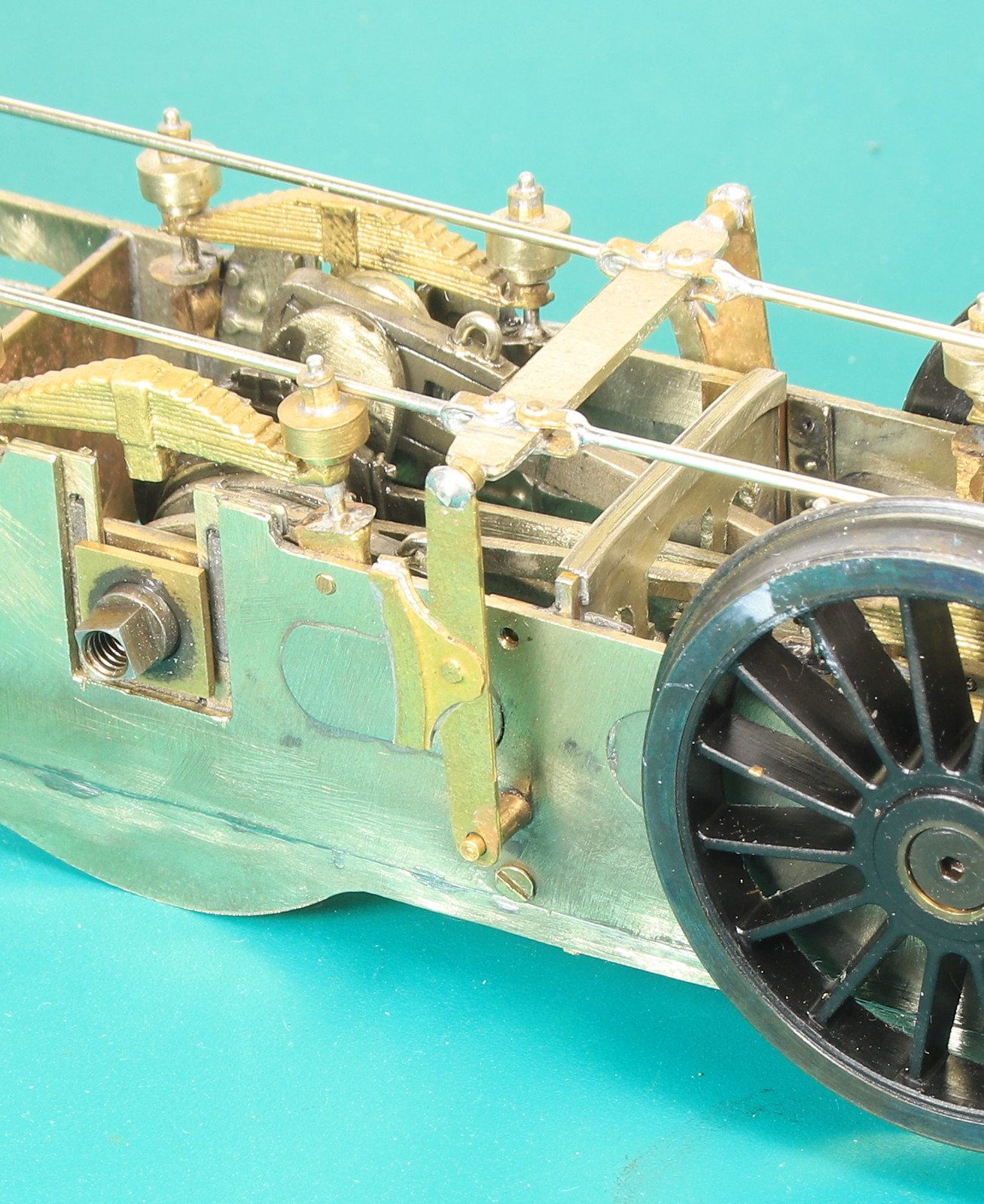
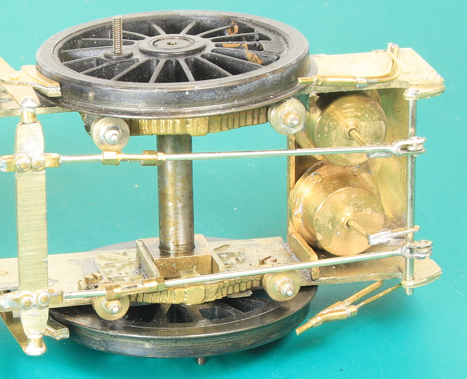
By Coincidence I had cause to remove the brakes this morning so I took a couple of photos showing them apart.
This will hopefully make clear anything that my description left wanting.

Re: Gladiator LNER/BR J6 - Inside Motion Now Working
Posted: Sun Jul 10, 2022 9:22 pm
by Robpulham
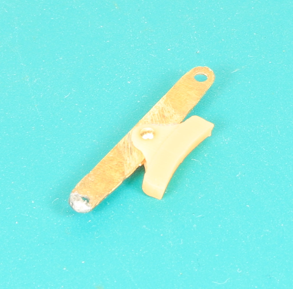
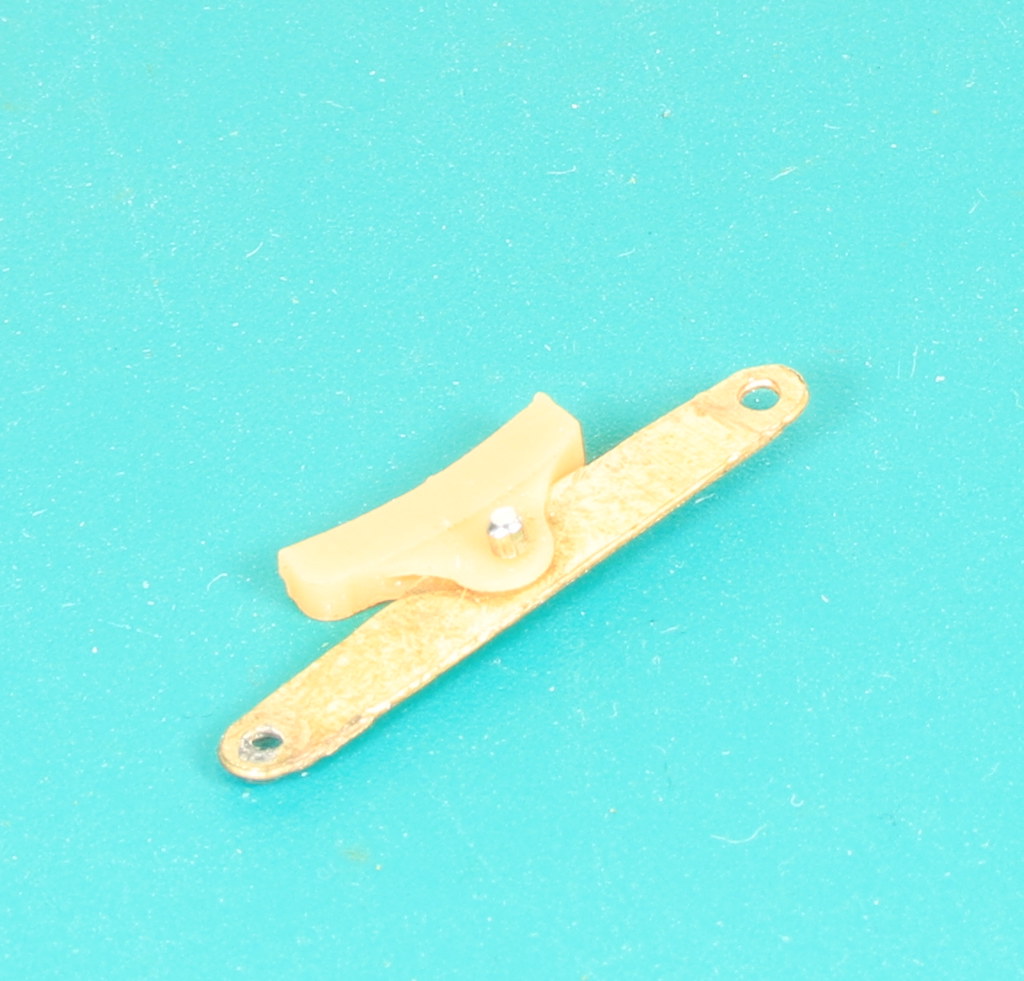
I wasn't really happy with how far away from the wheels the brake shoes needed to be to ensure that they didn't short. I rew up some brake shoes in Fusion and a friend kindly printed them off for me.
Today I had the chance to test fit one of them. After checking that I hadn't messed up and that the etched hanger would go between the flanges. I bit the bullet, unsoldered the etched overlay and cut of the brake shoe from the hanger.
The next question was how to attach the printed brake shoes to the hangers. I hoped to have the shoes free to move and after considering and discounting various options which involved superglue I settled on a dressmakers pin and short length of microbore tube soldered to the pin and then filed down.
Re: Gladiator LNER/BR J6 - Inside Motion Now Working
Posted: Mon Jul 11, 2022 12:46 am
by john coffin
You do realise that now you are going to have to make the brake standard work, and the next
stage then is a robot man to operate the brakes in manual mode?????????
Re: Gladiator LNER/BR J6 - Inside Motion Now Working
Posted: Mon Jul 11, 2022 6:04 am
by jwealleans
He doesn't need encouraging.....
Re: Gladiator LNER/BR J6 - Inside Motion Now Working
Posted: Thu Jul 14, 2022 5:14 pm
by Robpulham
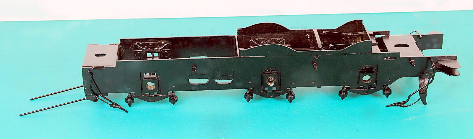
I got to fitting the rest of the 3D printed brake shoes to the J6 brake hangers today and then refitted them onto the pull rods. I don't think I have shown the loco sat on the body since it's pretty much complete. Just a few final bits like wiring it up and testing it before painting the chassis and weathering the whole thing


I also fitted the back head a couple of weeks ago but didn't take any photos
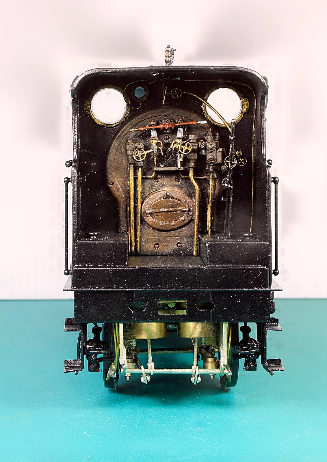
The rear view shows that making up the brake cylinders was worth it as they are quite visible when the loco is separated from it's tender.
Re: Gladiator LNER/BR J6 - Inside Motion Now Working
Posted: Fri Jul 15, 2022 8:45 am
by Horsetan
john coffin wrote: ↑Mon Jul 11, 2022 12:46 am
You do realise that now you are going to have to make the brake standard work, and the next
stage then is a robot man to operate the brakes in manual mode?????????
I was wondering if the brake shoes could be used as extra pickups, but these ones are insulated.....
Re: Gladiator LNER/BR J6 - Inside Motion Now Working
Posted: Fri Jul 15, 2022 5:47 pm
by Robpulham
Over on Western Thunder there was some discussion on the merits or not of Slaters Plunger pickups from a gent who had used them for the first time I mentioned that I was about to wire up the tender for the J6 with Slaters Plunger pickups and I offered to take photos as I went along. I thought they may be of use to someone else who may be contemplating using them but hasn't seen them before
First I guesstimated the lengths of wire needed to reach from the plunger to the connections on a piece of Vero Board. These I soldered to the tags provided with the plungers

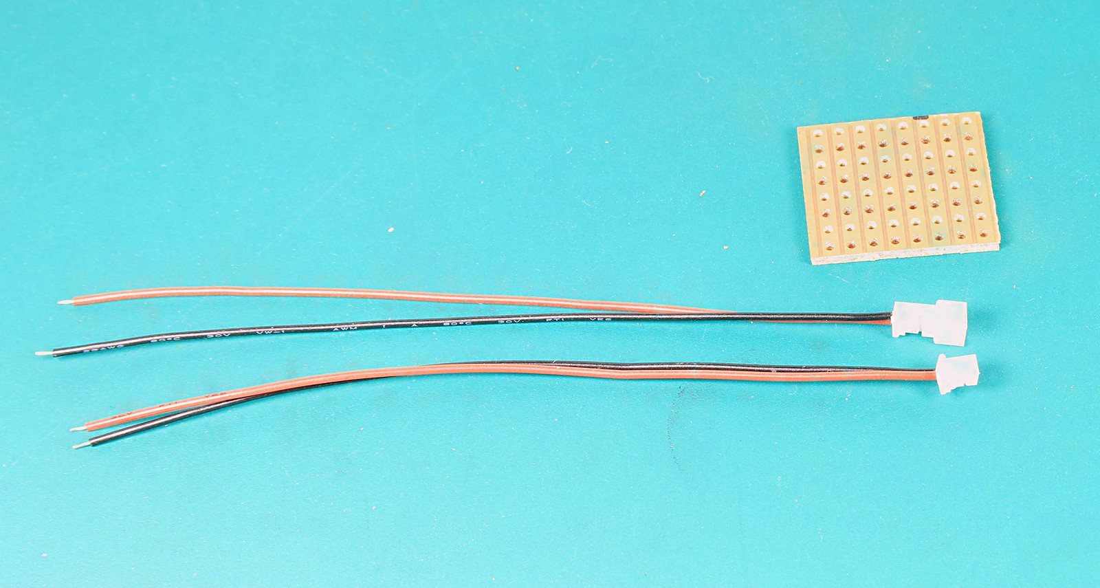
Connection between the tender and loco is to be by a mini plug sold for PC's and bought via eBay some time ago.
One thing that makes life a little easier when dealing with the 12BA nuts on Slaters Plungers is a pair of flat 12BA spanners available from Eileen's Emporium

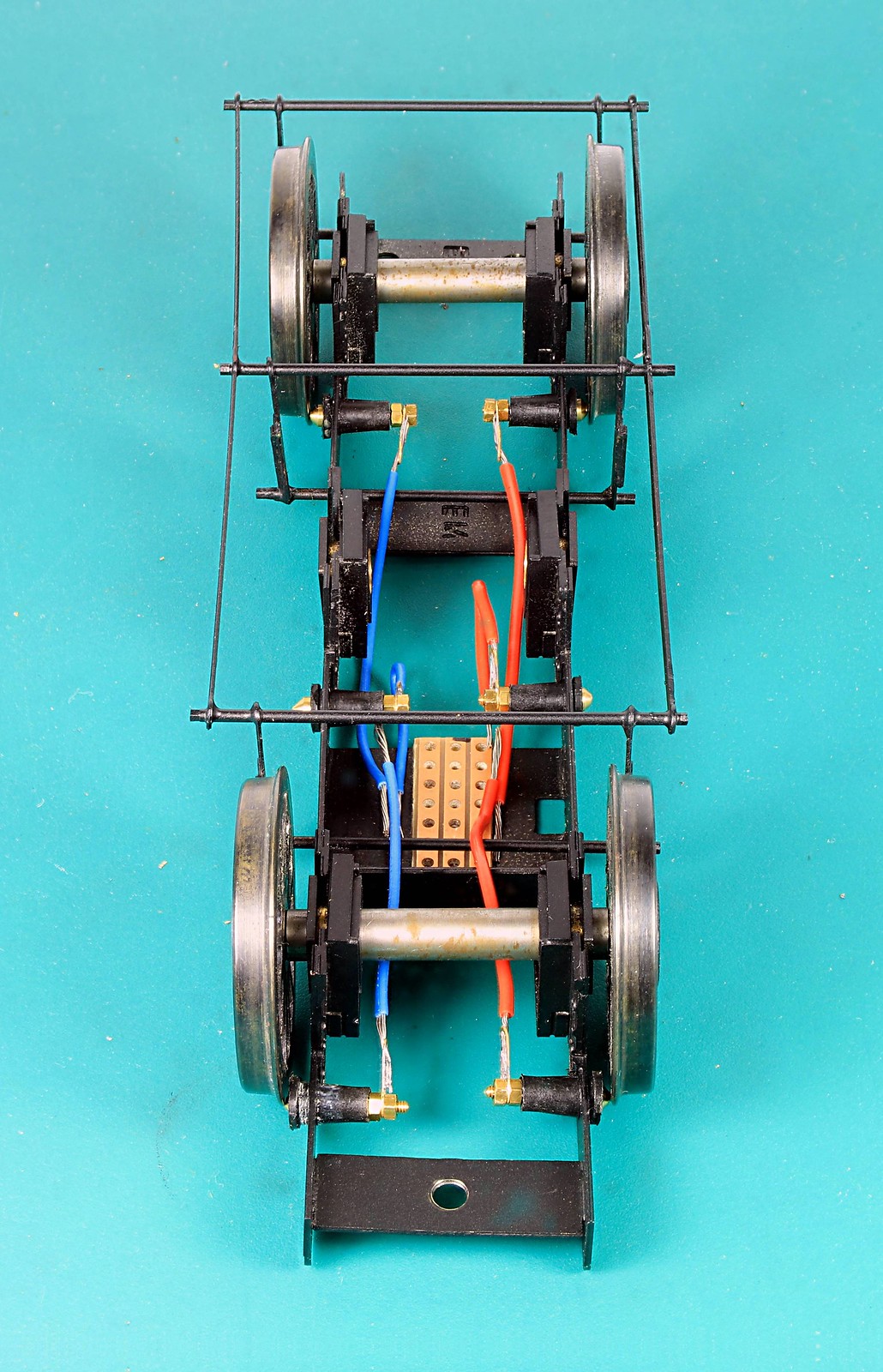
Here it is all wires connected to the plungers and ready to solder to the Vero Board

Finally all wired up. - The observant amongst you will note that the size of the Vero board has changed in the last photo. I made a right pigs ear of soldering the first piece managing to bridge the gaps between the strips with solder so I did it again. Thankfully I hadn't got all the wires on before I cocked it up.
Re: Gladiator LNER/BR J6 - Inside Motion Now Working
Posted: Fri Jul 15, 2022 11:36 pm
by manna
G'Day Gents
I bought some of those connectors from e-bay a couple of years ago, great idea, but I though they were to big for 00 gauge locos
manna
Re: Gladiator LNER/BR J6 - Inside Motion Now Working
Posted: Thu Jul 21, 2022 9:58 pm
by Robpulham
Not too much done on the J6 this week but it's almost there now.
I had a bit of a fright when I fitted the motor and I couldn't get the body on but thankfully I had just put it in the wrong way round.
What it did need is a motor mount/steady to stop it moving backwards and forwards inside the body. I cut a small piece of nickel sheet as a slding fit between the frames and then cut out the mounting hole. I worked out where I needed to fold it and then decided to give the bending shear on the MiniFormit a try. I am pleased o say it bend it perfectly. Not being used to using it, to make bends. I didn't follow the bend through to a right angle. instead I finished it off in my hold and fold.

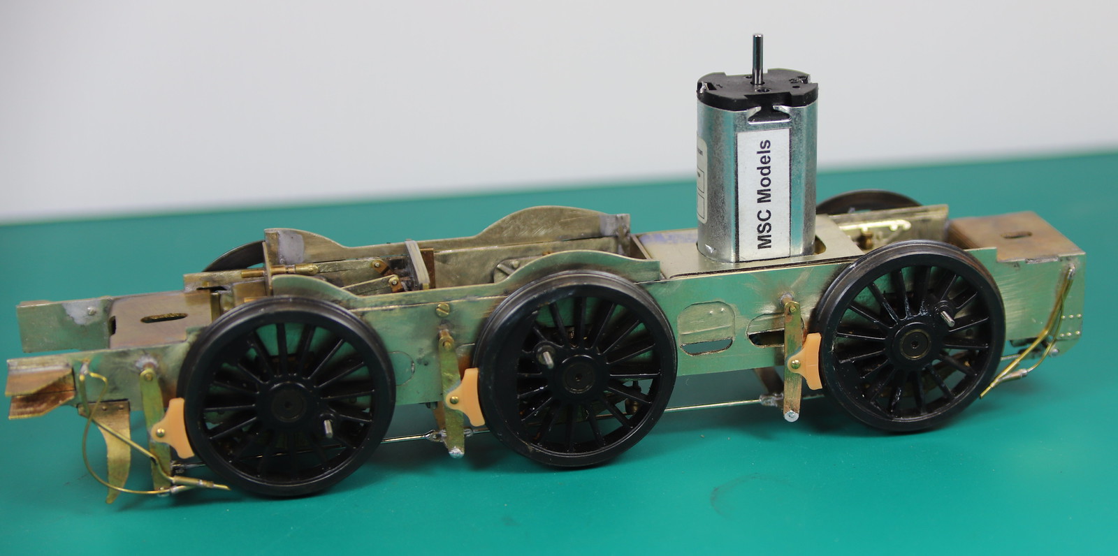
I just need to solder it in now.
Re: Gladiator LNER/BR J6 - Inside Motion Now Working
Posted: Thu Aug 04, 2022 10:45 am
by Robpulham
Contrary to my last post I decided to see if I could make the motor mount removable. It proved not too difficult to add a screw and retaining nut to the adjacent frame spacer.

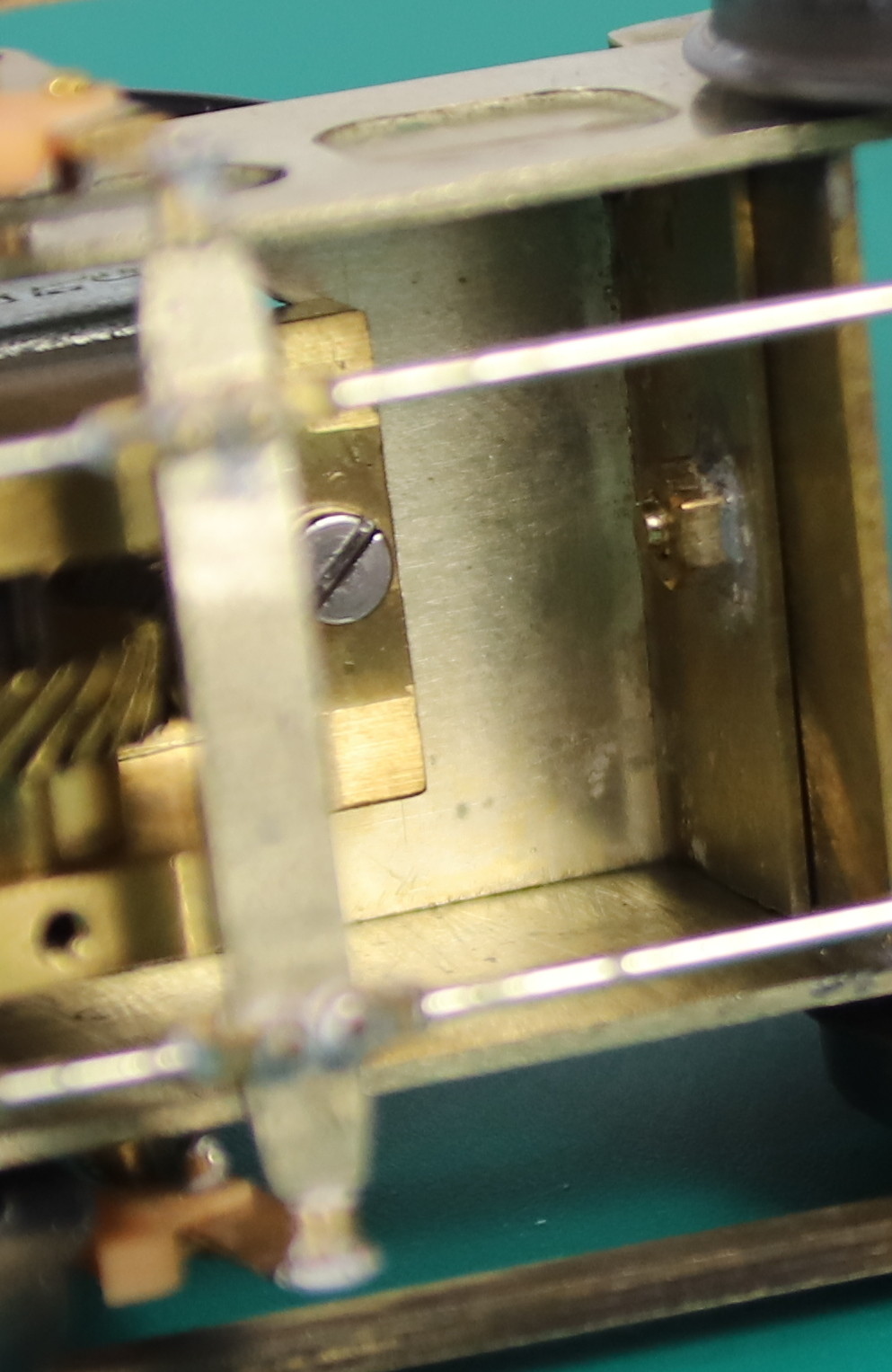
The motor mount also made a convenient place to mount a piece of Vero board which means that I can now remove both the motor and mount together without having to unsolder any wires which I count as an unexpected win.
The hole in the tender plate which supports the bottom end of the pivot pin was much bigger than the screw itself (8BA) and after fiddling around for about 10 minutes trying to get the screw to engage in the nut I decided to turn a small bush to centre it.


I am getting dangerously near to painting the chassis.
Re: Gladiator LNER/BR J6 - Inside Motion Now Working
Posted: Sun Aug 07, 2022 10:20 am
by Robpulham
The wind dropped enough for a couple of short bursts of painting outside. This enabled me to get the chassis primed and then top coated.
I also did all the other little bits that I missed when doing the body and tender, fall plate, doors etc.
Before risking gumming up the motion I asked Warren Haywood and Tony Geary how they painted inside motion. Tony hand paints his and Warren sprays it. Warren did suggest that since the brief for this is weathered black rather than red to metal black it. Thinking this a good idea I had a go. I gave the chassis a liberal dose of acetone to hopefully remove all the oil then a liberal dose of Birchwood Casey Brass black. It kind of worked, the motion itself looked fine but the insides of the frames and motion plates etc. were quite patchy.
In the end I bit the bullet and lightly sprayed it with black etch primer. Thankfully it all still moves as it should but I did mask it before putting the final coat of the rest of the frames.
