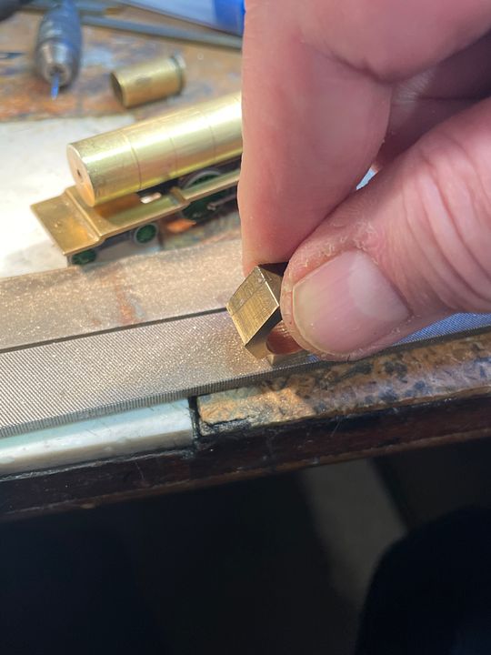
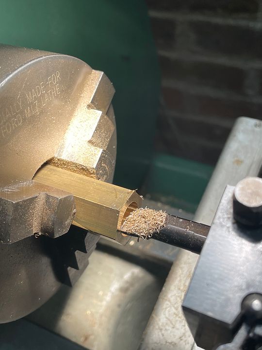
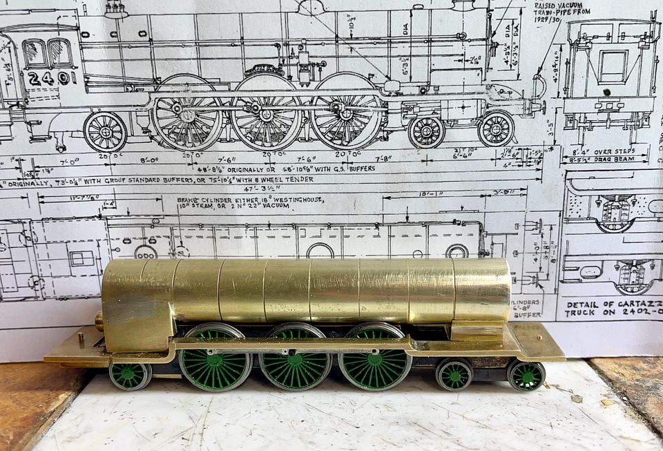
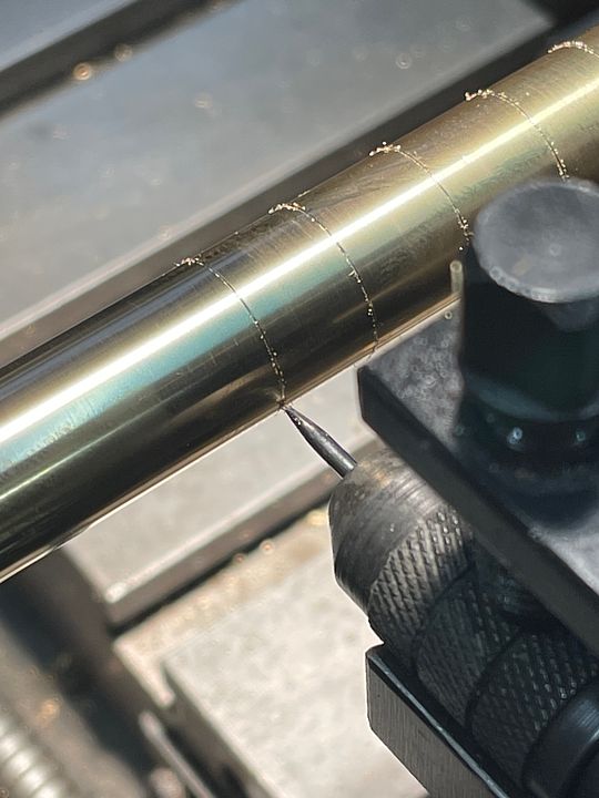
The bit of hex brass bar was drilled out and then bored to be a good fit on the smoke box.
[URL=htps://hosting.photobucket.com/images/p707/strq0672/0176B918-6A30-45FA-A9E0-E27BF21BF8B3.jpeg?width=960&height=720&fit=bounds]
[/URL]
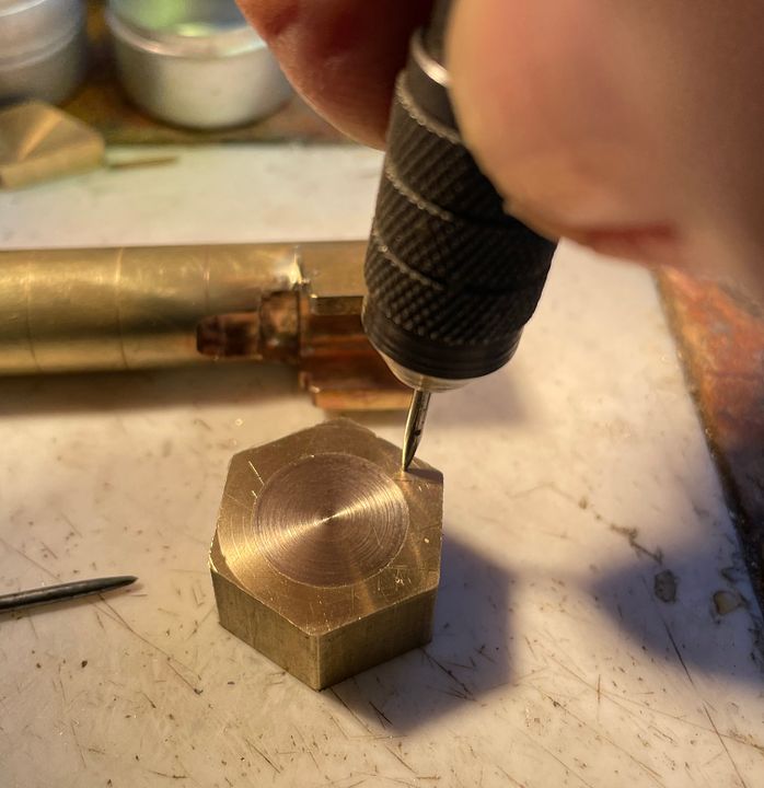
The advantage of the hex bar is that it is easy to hold in a chuck and can be parted off to the required length. The front face was very carefully marked out for the two holes that would be the radiused corners of the smoke box saddle. I use a gramophone needle ground to a pyramidal-shaped tip. That way it is easy to ‘drift’ the centre mark to where it’s needed, rotating the tip to deepen it in the correct position.
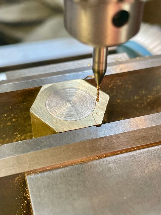
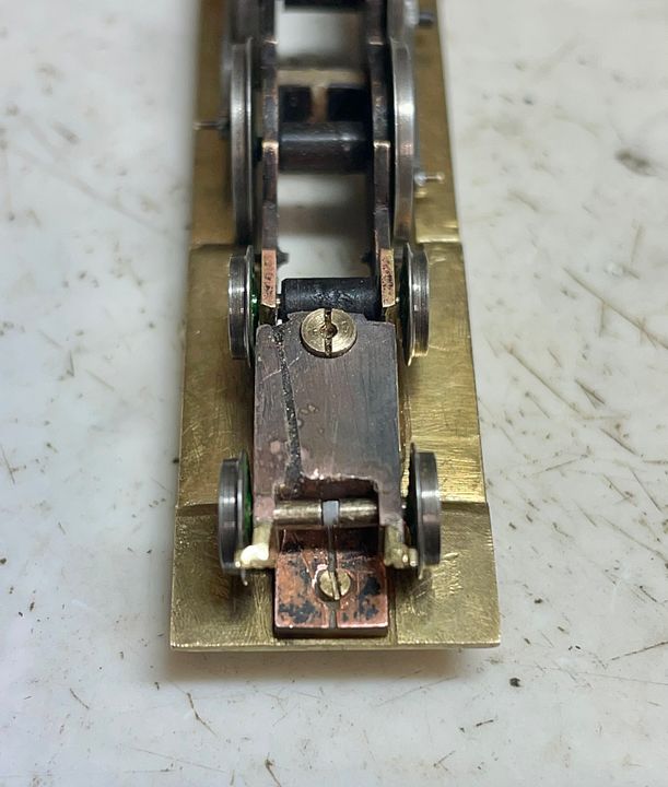
The marked up block was easy to set up in the vice - an advantage of using the hex stock. It’s a bit difficult to visually ‘spot’ a 2mm drill in precisely the right place, so the drilling position was checked using a 0.7mm drill. The brass plug was a precaution against any lateral distortion when drilling with the larger size.
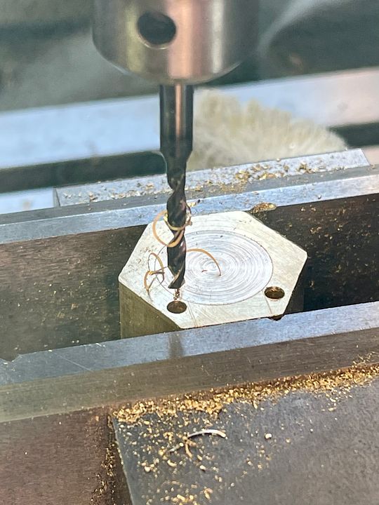
Once satisfied with the centering the holes were drilled at 2mm diameter.
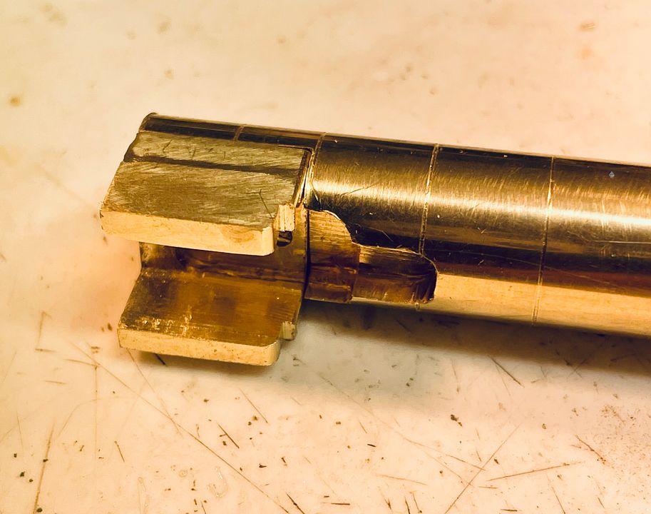
The sides of the holes were milled away.
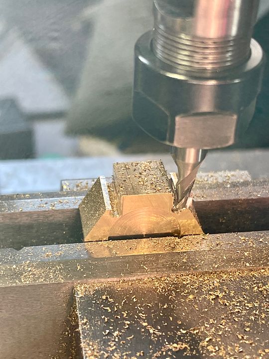
The side of the holes were used to guide a file as it cut down to the final position. It’s always useful having sharp files with safe edges.
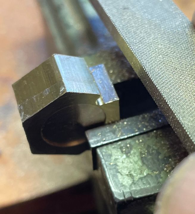
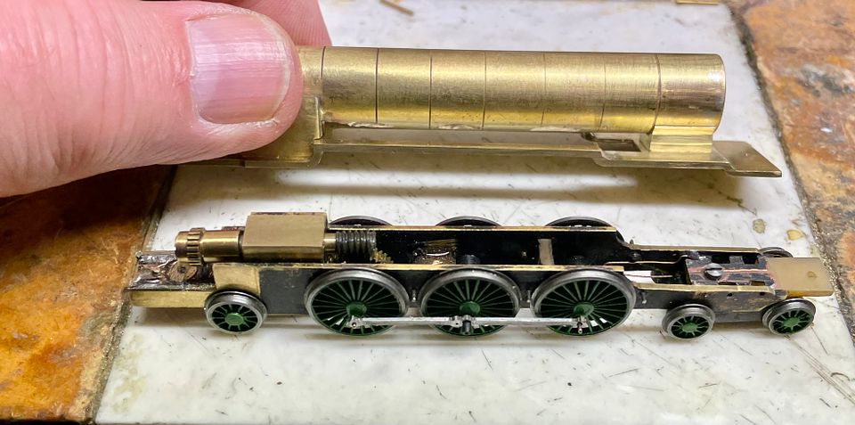
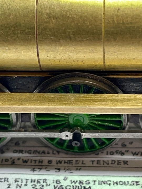
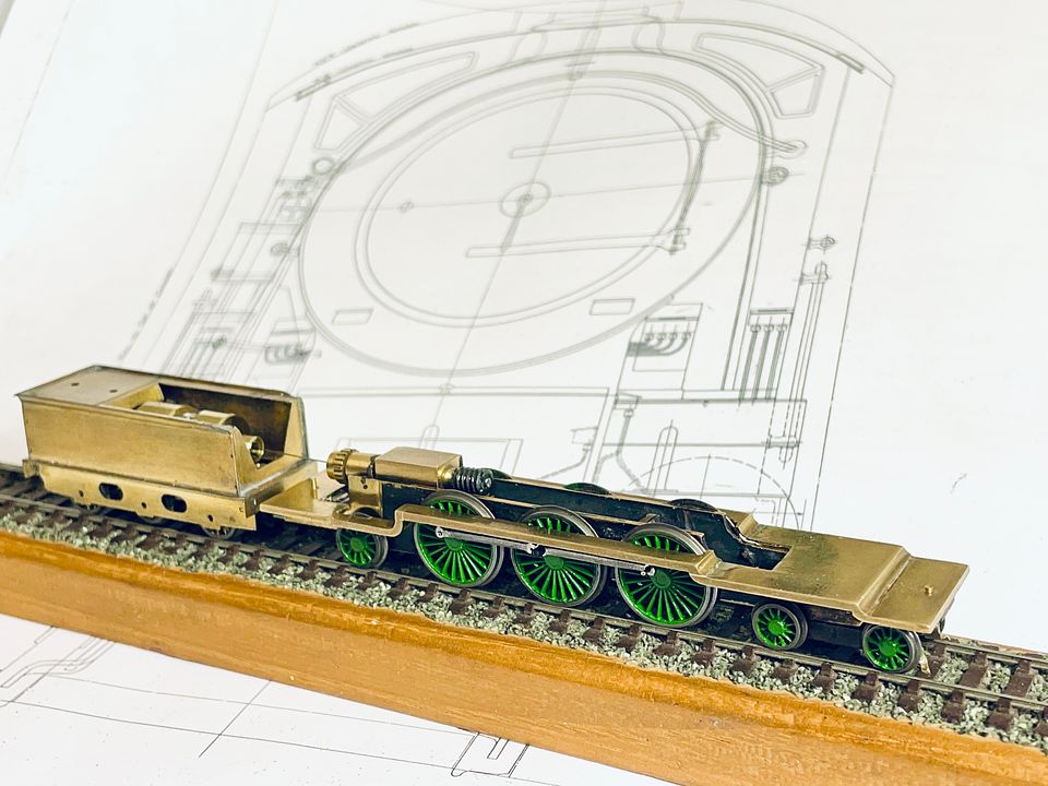
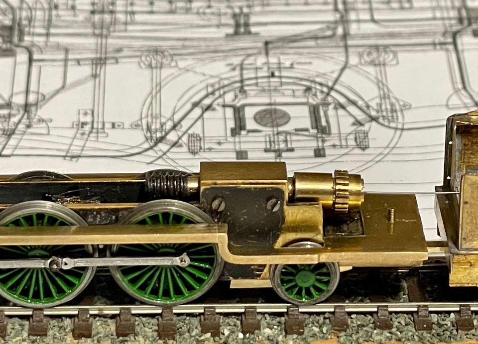
The excess hex bar made a good handle as the base was carefully reduced in depth to maintain the correct height of the boiler and smokebox.
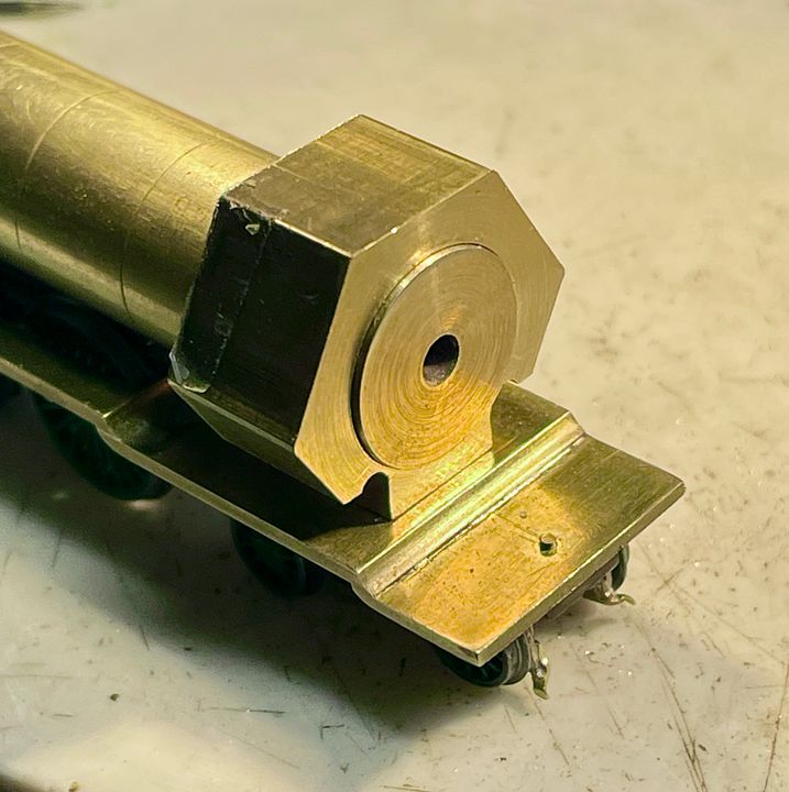
The unwanted parts of the bar were removed using a diamond slitting disc and the flange smoothed into the up right part of the saddle. This was also rebated at the sides to take the scale frames that are above running plate level.
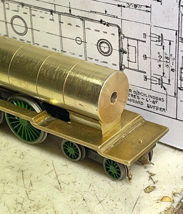
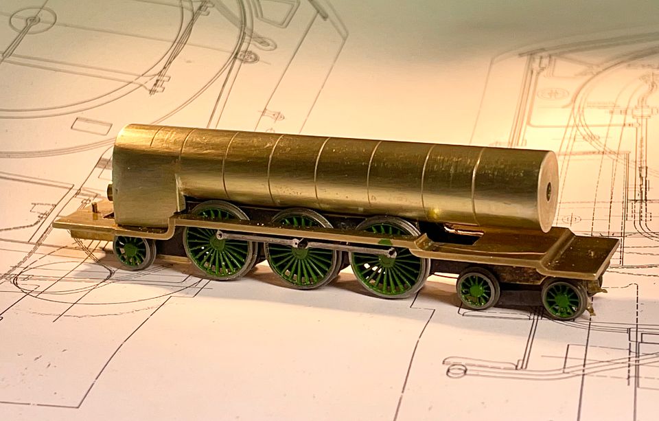
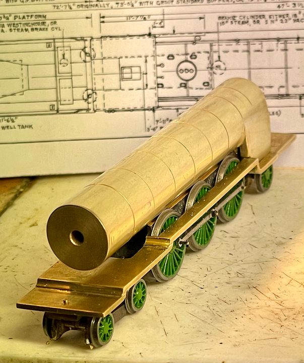
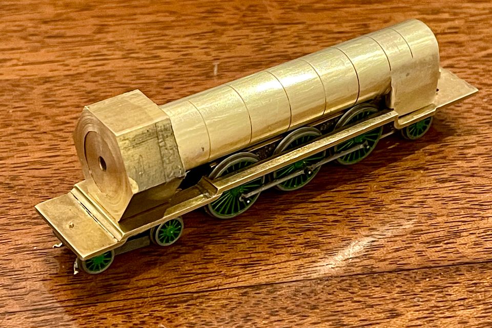
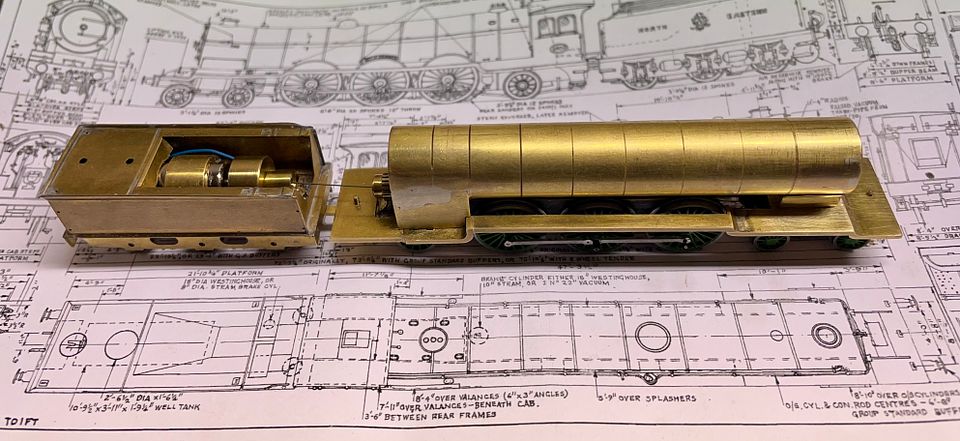
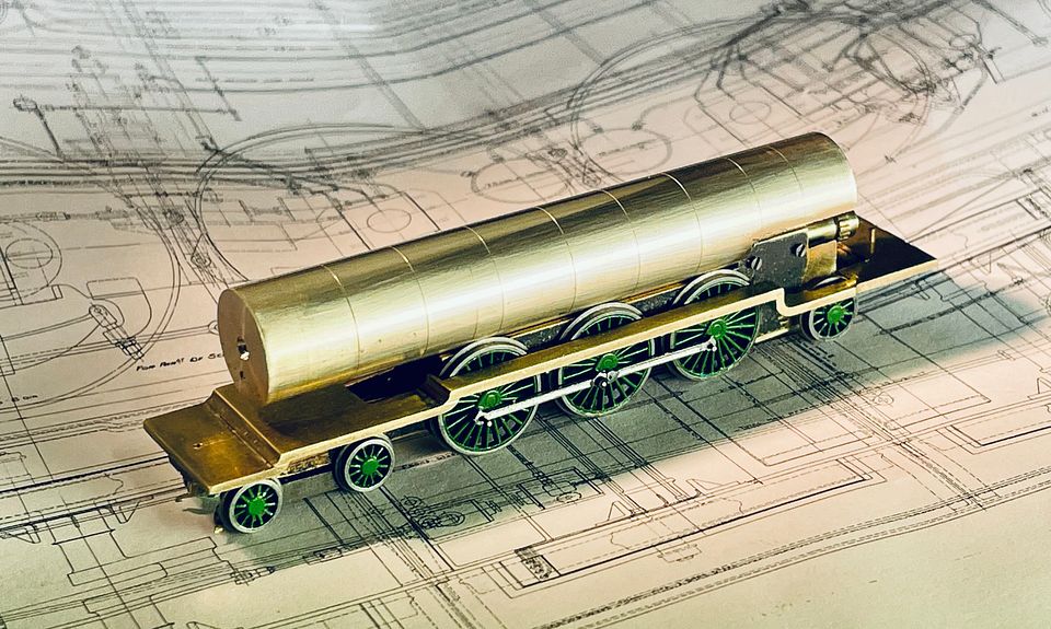
She’s beginning to look like a Skittle Alley now.
Bit of a long post this one, but I thought some of my ways of working might be of interest. The next job will be to get it all bolted together.
Tim
 [/URL]
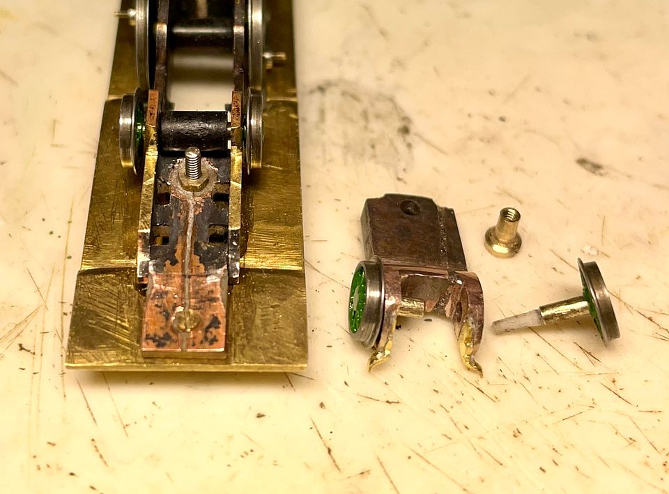

 [/URL]
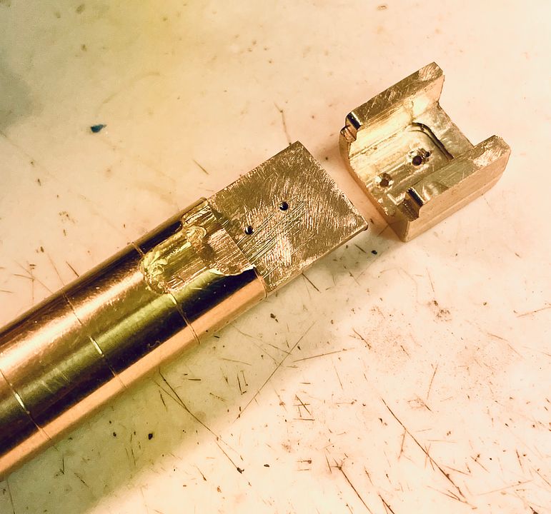 [/URL]