Copenhagen Fields & TFW’s workshop
Moderators: 52D, Tom F, Rlangham, Atlantic 3279, Blink Bonny, Saint Johnstoun, richard
-
jwealleans
- LNER A4 4-6-2 'Streak'
- Posts: 4223
- Joined: Wed Oct 25, 2006 8:46 am
Re: Copenhagen Fields & TFW’s workshop
I was going to say it's watchmaking, but I think even a watchmaker might tip his hat.
-
Atlantic 3279

- LNER A4 4-6-2 'Streak'
- Posts: 6541
- Joined: Fri Jun 26, 2009 9:51 am
- Location: 2850, 245
Re: Copenhagen Fields & TFW’s workshop
I'm repeatedly amazed at the accuracy, bearing in mind that many of the parts are the same sort of size as the bits that I frequently put down on my bench (or carelessly "ping" them during handling) and then cannot find anywhere on the bench, only moments later, and still cannot find after spending time searching the carpet and swearing!
Most subjects, models and techniques covered in this thread are now listed in various categories on page1
Dec. 2018: Almost all images that disappeared from my own thread following loss of free remote hosting are now restored.
Dec. 2018: Almost all images that disappeared from my own thread following loss of free remote hosting are now restored.
-
Tim Watson
- GER D14 4-4-0 'Claud Hamilton'
- Posts: 312
- Joined: Mon Oct 24, 2016 11:37 am
Re: Copenhagen Fields & TFW’s workshop
Thank you for the kind comments. I think half the challenge with making small parts is holding them
to work on. To that end, I have good tweezers, a Swiss Bergeon vice and a recently-acquired Eclipse tool maker’s vice. Good quality Swiss files and piercing saw blades are also a must. Clockmaking maybe, watch making is in a different league.
Tim
to work on. To that end, I have good tweezers, a Swiss Bergeon vice and a recently-acquired Eclipse tool maker’s vice. Good quality Swiss files and piercing saw blades are also a must. Clockmaking maybe, watch making is in a different league.
Tim
-
Tim Watson
- GER D14 4-4-0 'Claud Hamilton'
- Posts: 312
- Joined: Mon Oct 24, 2016 11:37 am
Re: Copenhagen Fields & TFW’s workshop
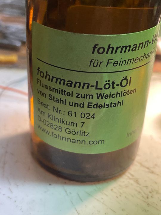
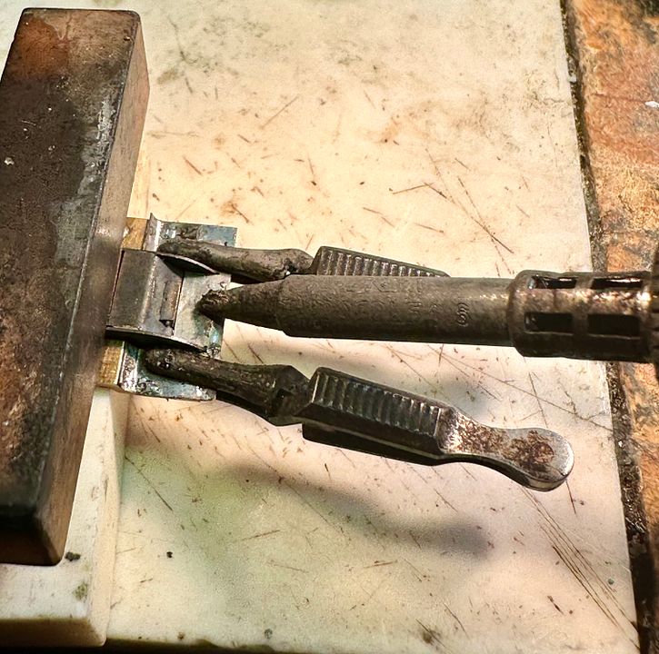
Not much to show with this post, but the front running plate has now been soldered to the brass core. As before, I used chemical blacking to ensure that the frames and piano front do not become irretrievably fixed in place. The front body fixing screw was also blacked and screwed into place to prevent the thread from filling with solder. The individual components were tinned with solder, the steel fluxed using a special steel flux which I sourced from Germany.
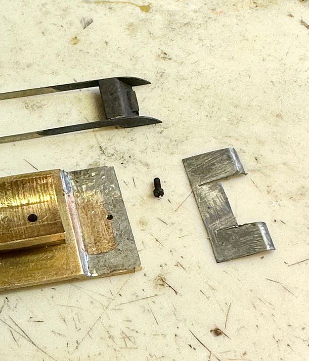
The components were held in place using ceramic blocks and miniature towel clips whilst the ERSA soldering station was cranked up to 450 deg C and applied to the steel plate with plenty of flux.
The flux is quite acidic and so after soldering the whole assembly was boiled in a saucepan of water for five minutes (don’t do this if you have white metal or low melting point solder!).
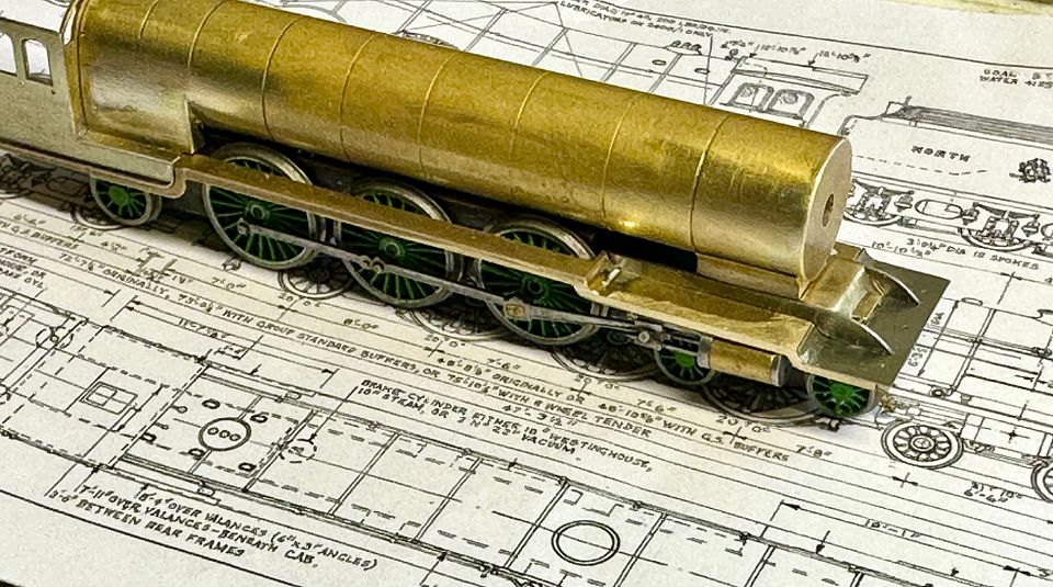
Next job will be the second running plate and reversing mechanism.
Tim
The components were held in place using ceramic blocks and miniature towel clips whilst the ERSA soldering station was cranked up to 450 deg C and applied to the steel plate with plenty of flux.
The flux is quite acidic and so after soldering the whole assembly was boiled in a saucepan of water for five minutes (don’t do this if you have white metal or low melting point solder!).
Next job will be the second running plate and reversing mechanism.
Tim
-
Mercator II
- GCR O4 2-8-0 'ROD'
- Posts: 513
- Joined: Mon Nov 03, 2008 12:14 pm
- Location: Lincolnshire
Re: Copenhagen Fields & TFW’s workshop
Truly blown away Tim by your work. Such craftsmanship in 2mm is beyond my belief
Thank you for taking the time to share your process & progress
Hopefully will get to see it running at Warley in November
Thank you for taking the time to share your process & progress
Hopefully will get to see it running at Warley in November
oOo
Brian
Garage Hobbit!!
Modelling in 00 on my heritage line, very GCR inspired
Brian
Garage Hobbit!!
Modelling in 00 on my heritage line, very GCR inspired
-
Tim Watson
- GER D14 4-4-0 'Claud Hamilton'
- Posts: 312
- Joined: Mon Oct 24, 2016 11:37 am
Re: Copenhagen Fields & TFW’s workshop
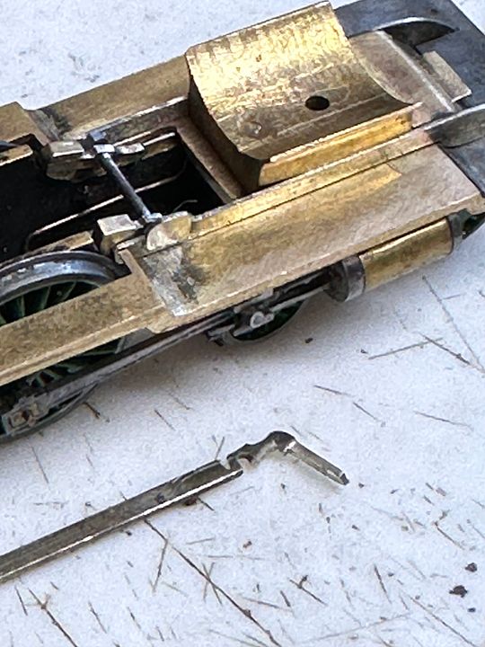
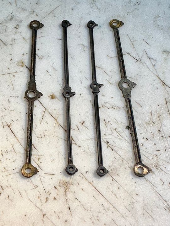
Over the last couple of days I’ve been making some of the between-the-frames parts for the Raven 4-6-2 class. These engines were fitted with steam reverse when new and a light-coloured plate was visible on the drivers’ (RH) side: this was the cover for a travel-limiting lever. On both sides, the balance weight on the weigh shaft was visible just in front of the splashers in full forward gear. All of this work will scarcely be visible, but might catch the eye when painted.
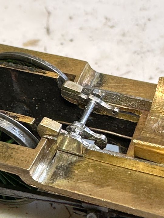
It took a while to work out the mechanism at the top end, but zooming in on the GA helped:
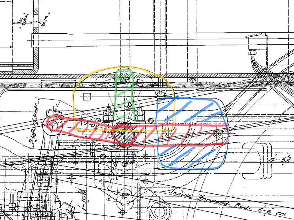
Blue balance weight
Red lifting arm
Green limiter arm
Yellow backing plate.
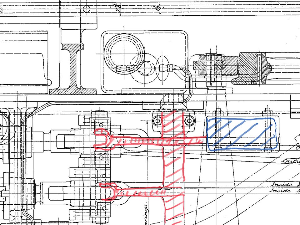
Blue balance weight
Red lifting arms and weigh shaft.
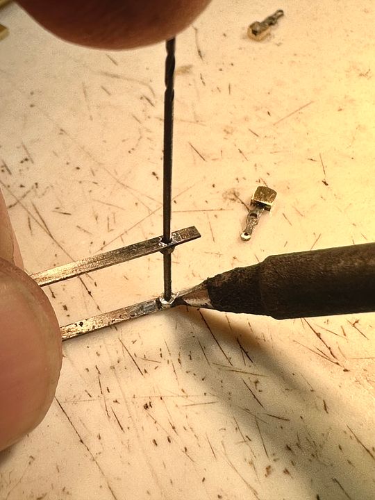
The lifting arms and balance weights were made as one piece, silver soldered together and then separated.
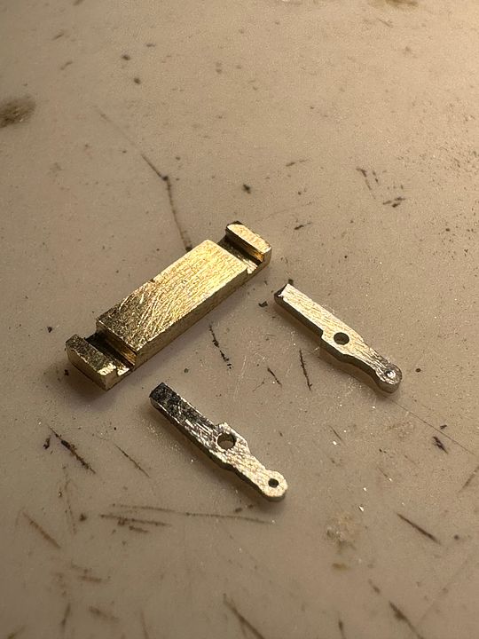
The trunnions that support the weigh shaft were reamed out 16BA nuts soft soldered to the inside of the frames. A hole was drilled on one side (where the cover plate is fixed) and that was used to align the nut on the other side, which was stabilised with a drill shank whilst soldering. These are much better than cocktail sticks as they don’t burn, fit precisely and will not take soft solder.
The cover plate was soldered on being made from a scrap of NS etch, but with a handle to hold it in place whilst soldering, it was also rebated on the back edge to aid location. The sacrificial handle was then twisted / cut off.
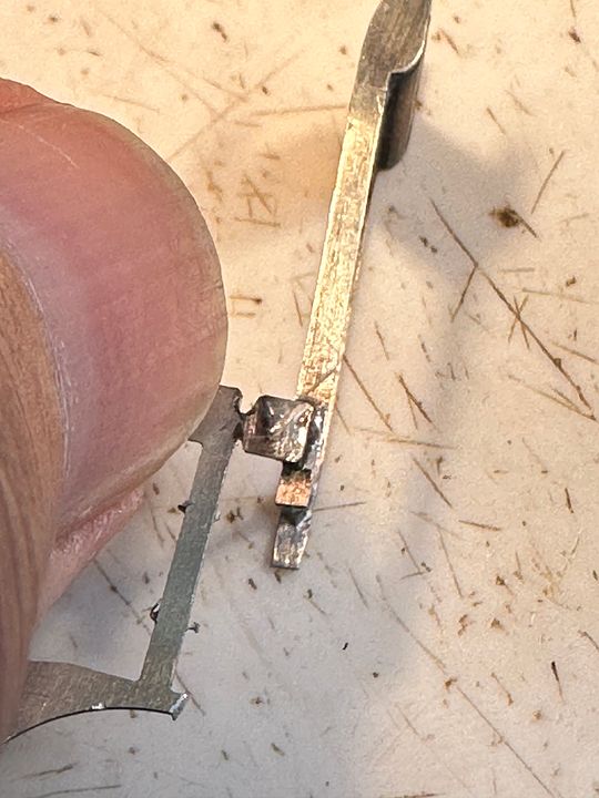
The lifting arm for the inside cylinder valve gear was made from NS CG rail and notched so that it could be clipped into place.
Soldering it onto the shaft was aided by burying the lift link into a charcoal block to hold it whilst the tinned components were quickly heated with a hot iron and plenty of flux. The long handle was subsequently removed by twisting it off.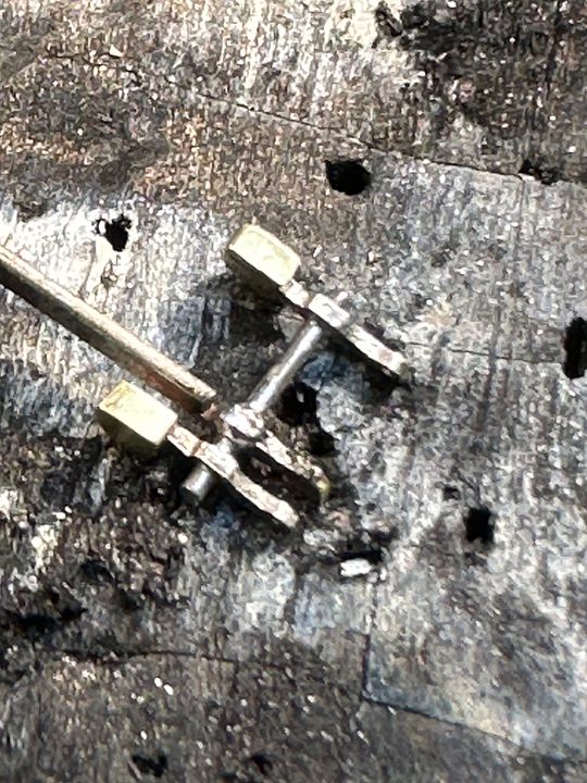
The whole assembly really doesn’t show up that much, but will when painted - probably vermillion for the shaft and weights.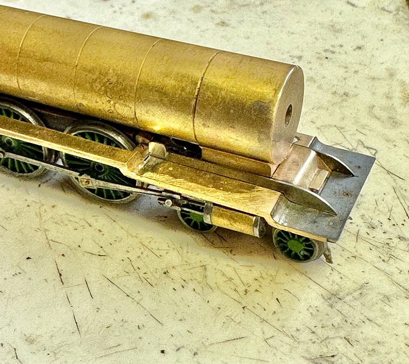
The question, is, what was the colour of the limiter backing plate?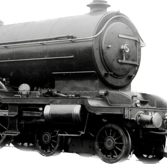
I suspect at least vermillion. What colour were NER engines between the frames? Answers on a postcard…
Tim
It took a while to work out the mechanism at the top end, but zooming in on the GA helped:
Blue balance weight
Red lifting arm
Green limiter arm
Yellow backing plate.
Blue balance weight
Red lifting arms and weigh shaft.
The lifting arms and balance weights were made as one piece, silver soldered together and then separated.
The trunnions that support the weigh shaft were reamed out 16BA nuts soft soldered to the inside of the frames. A hole was drilled on one side (where the cover plate is fixed) and that was used to align the nut on the other side, which was stabilised with a drill shank whilst soldering. These are much better than cocktail sticks as they don’t burn, fit precisely and will not take soft solder.
The cover plate was soldered on being made from a scrap of NS etch, but with a handle to hold it in place whilst soldering, it was also rebated on the back edge to aid location. The sacrificial handle was then twisted / cut off.
The lifting arm for the inside cylinder valve gear was made from NS CG rail and notched so that it could be clipped into place.
Soldering it onto the shaft was aided by burying the lift link into a charcoal block to hold it whilst the tinned components were quickly heated with a hot iron and plenty of flux. The long handle was subsequently removed by twisting it off.
The whole assembly really doesn’t show up that much, but will when painted - probably vermillion for the shaft and weights.
The question, is, what was the colour of the limiter backing plate?
I suspect at least vermillion. What colour were NER engines between the frames? Answers on a postcard…
Tim
-
Atlantic 3279
- LNER A4 4-6-2 'Streak'
- Posts: 6541
- Joined: Fri Jun 26, 2009 9:51 am
- Location: 2850, 245
Re: Copenhagen Fields & TFW’s workshop
More fabulous micro-surgery. Could that plate have a slightly dulled burnished steel finish?
Most subjects, models and techniques covered in this thread are now listed in various categories on page1
Dec. 2018: Almost all images that disappeared from my own thread following loss of free remote hosting are now restored.
Dec. 2018: Almost all images that disappeared from my own thread following loss of free remote hosting are now restored.
-
Tim Watson
- GER D14 4-4-0 'Claud Hamilton'
- Posts: 312
- Joined: Mon Oct 24, 2016 11:37 am
Re: Copenhagen Fields & TFW’s workshop
Possibly, but would be tricky to keep clear of rust, as there isn’t much oil flying around that area.
Tim
Tim
Re: Copenhagen Fields & TFW’s workshop
Tim Watson wrote: ↑Sat Sep 23, 2023 11:38 am Over the last couple of days I’ve been making some of the between-the-frames parts for the Raven 4-6-2 class. These engines were fitted with steam reverse when new and a light-coloured plate was visible on the drivers’ (RH) side: this was the cover for a travel-limiting lever. On both sides, the balance weight on the weigh shaft was visible just in front of the splashers in full forward gear. All of this work will scarcely be visible, but might catch the eye when painted.
"I am sure I have read somewhere?, that the weights were only visible in the Reverse setting?. Hence that is why they are not visible in the photos of them running ? " I am so glad my DJH A2 has solid footplate !!.
Lovely work either way.
Mick
-
Tim Watson
- GER D14 4-4-0 'Claud Hamilton'
- Posts: 312
- Joined: Mon Oct 24, 2016 11:37 am
Re: Copenhagen Fields & TFW’s workshop
I asked about the visibility of the weights in forward gear in the loco section of the forum and was pointed towards a photo of 2400 at Cawton in 1926 (copyright Rail Online Archive). This shows the weight clearly visible with the engine at speed. A section for illustrative purposes shown here:
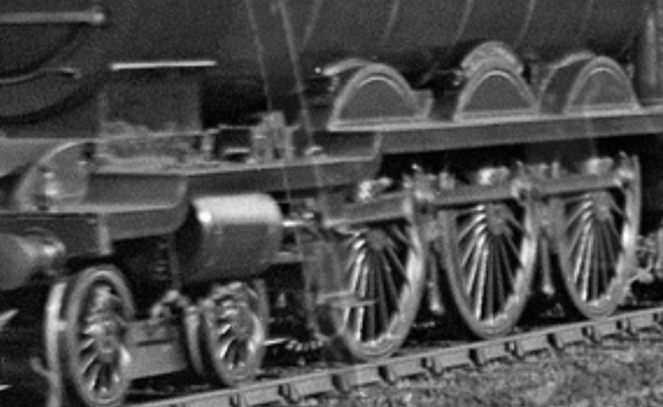
The loco will be headed north through Belle Isle on CF, so I expect it will be in full forward for the climb up the Holloway Bank.
Tim
The loco will be headed north through Belle Isle on CF, so I expect it will be in full forward for the climb up the Holloway Bank.
Tim
-
Tim Watson
- GER D14 4-4-0 'Claud Hamilton'
- Posts: 312
- Joined: Mon Oct 24, 2016 11:37 am
Re: Copenhagen Fields & TFW’s workshop
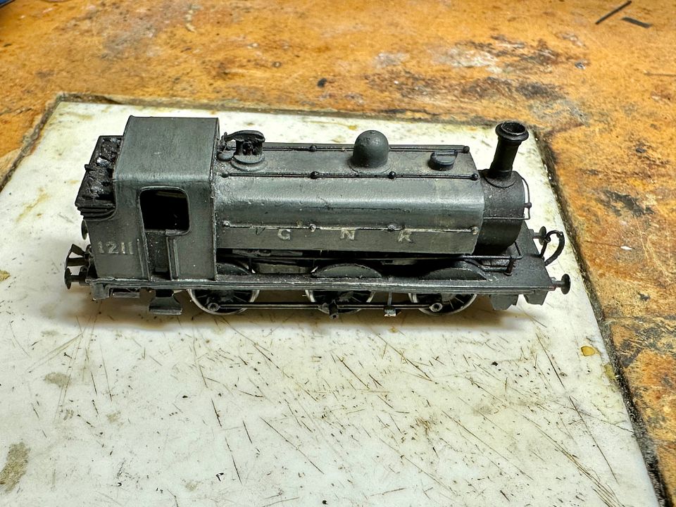
I have spent a very few hours on the easy conversion of the Sonic Models J50 to FS. This photo shows the end result which, quite frankly, is not greatly different to the original.
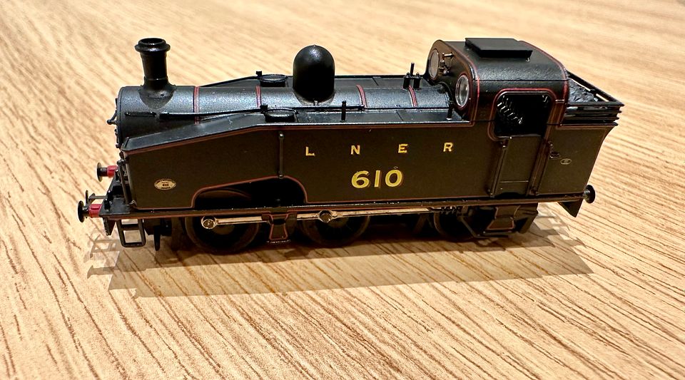
The wheel profile is very fine, as is often the way with modern N gauge. However the flanges, whilst not deep are too thick for FS standards. The individual wheels were mounted in a step collet and the backs of the flanges thinned down. The TC drill stub in the tailstock helped to make sure the wheel didn’t fly out by steadying it.
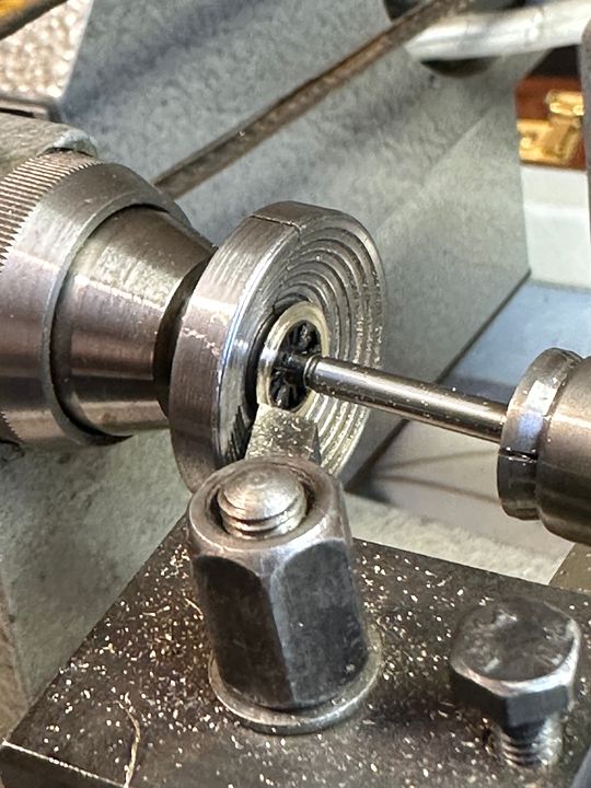
The reduction in flange thickness can be seen here. The wheels are interesting in that they consist of a brass casting for the rim and a few of the back spokes of the wheel and stub axle which is 3mm diameter and acts as the bearing surface running in phosphor bronze bearings. The front spokes of the wheel are plastic and bored 1.1mm for a plain steel axle.
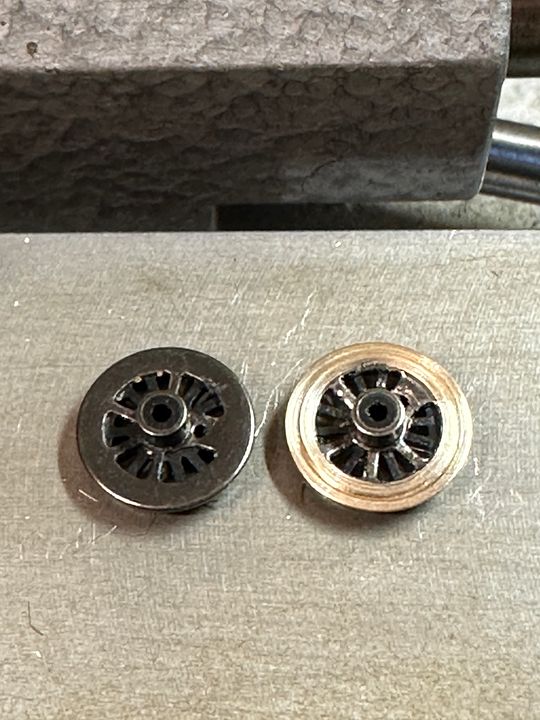
The wheels were then mounted in a 3mm collet and a little bit removed from the front face to narrow the tread (I didn’t take a picture of this procedure). The wheels were then chemically blackened.
The wheels + 10-20 thou black styrene washer and then bearings were re-mounted on the axles at the wider FS back to back measurement and quartered by eye. The washers were to reduce some of the increased side play with an increased thickness needed on the back wheels where the steps and plumbing become rather close. Even so, these benefit from a bit of paring away with a sharp scalpel blade.
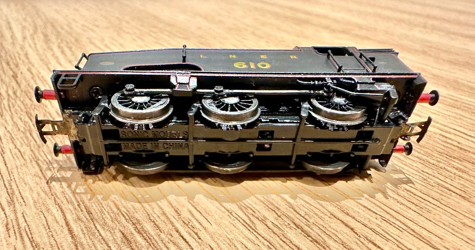
The coupling rods are simply held in place with tight fitting pins and are commendably thin. A few strokes with a file improved them further by removing the etch cusp and
thinning them down a little.
The end result is a very easily converted loco. All of the operations I have done could be undertaken with a simple lathe - even a mounted drill and sharp files - as there is no interference with wheel concentricity. The wheels are slightly chunkier than the fine scale standard but more than acceptable on a large layout like Copenhagen Fields. I am looking forward to more superb engines from this source!
Tim
The wheel profile is very fine, as is often the way with modern N gauge. However the flanges, whilst not deep are too thick for FS standards. The individual wheels were mounted in a step collet and the backs of the flanges thinned down. The TC drill stub in the tailstock helped to make sure the wheel didn’t fly out by steadying it.
The reduction in flange thickness can be seen here. The wheels are interesting in that they consist of a brass casting for the rim and a few of the back spokes of the wheel and stub axle which is 3mm diameter and acts as the bearing surface running in phosphor bronze bearings. The front spokes of the wheel are plastic and bored 1.1mm for a plain steel axle.
The wheels were then mounted in a 3mm collet and a little bit removed from the front face to narrow the tread (I didn’t take a picture of this procedure). The wheels were then chemically blackened.
The wheels + 10-20 thou black styrene washer and then bearings were re-mounted on the axles at the wider FS back to back measurement and quartered by eye. The washers were to reduce some of the increased side play with an increased thickness needed on the back wheels where the steps and plumbing become rather close. Even so, these benefit from a bit of paring away with a sharp scalpel blade.
The coupling rods are simply held in place with tight fitting pins and are commendably thin. A few strokes with a file improved them further by removing the etch cusp and
thinning them down a little.
The end result is a very easily converted loco. All of the operations I have done could be undertaken with a simple lathe - even a mounted drill and sharp files - as there is no interference with wheel concentricity. The wheels are slightly chunkier than the fine scale standard but more than acceptable on a large layout like Copenhagen Fields. I am looking forward to more superb engines from this source!
Tim
-
Tim Watson
- GER D14 4-4-0 'Claud Hamilton'
- Posts: 312
- Joined: Mon Oct 24, 2016 11:37 am
Re: Copenhagen Fields & TFW’s workshop
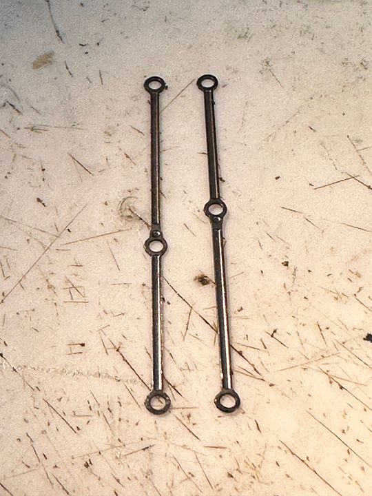
I have been working on an old timer today - the GNR J13 that Mark Fielder made from an old Beaver N gauge kit. It trundled around Copenhagen Fields for hundreds of miles, but ‘failed to proceed’ a few shows ago. The chassis is a heavily worn Graham Farish 57XX block, fitted with the late Neil Ballantine’s plastic moulded fine-scale replacements and a Maxon motor with 1:4 gear box, driving the original worm set. However, it is the coupling rods that have worn the most.
The holes had worn to be at least 50% bigger than they should be. They were replaced by a new set made from 2mm Scale Association etches.
What is quite remarkable is that the new rods fitted without any adjustment. The engine now trundles up and down the test track with a slight ambling gait, but then it always has.
It will be good to have a work horse back in the traces for our next show at the NEC in November. Attention is now turned to making the York Road station tube platform and hopefully another loop on the down goods line.
Tim
-
Atlantic 3279
- LNER A4 4-6-2 'Streak'
- Posts: 6541
- Joined: Fri Jun 26, 2009 9:51 am
- Location: 2850, 245
Re: Copenhagen Fields & TFW’s workshop
Those rare occasions when a job proves easier than expected are always nice.
Most subjects, models and techniques covered in this thread are now listed in various categories on page1
Dec. 2018: Almost all images that disappeared from my own thread following loss of free remote hosting are now restored.
Dec. 2018: Almost all images that disappeared from my own thread following loss of free remote hosting are now restored.
-
Hatfield Shed
- LNER A4 4-6-2 'Streak'
- Posts: 1666
- Joined: Fri Dec 23, 2011 3:34 pm
Re: Copenhagen Fields & TFW’s workshop
Fine as the mainline monsters are, I do like the 'maids of all work', that little Humpy is a beauty. It's long in service condition will contrast very well with the relatively new J50. I have been very pleased by the Sonic A5 in OO, to achieve the same crispness in RTR N is impressive.
-
Tim Watson
- GER D14 4-4-0 'Claud Hamilton'
- Posts: 312
- Joined: Mon Oct 24, 2016 11:37 am
Re: Copenhagen Fields & TFW’s workshop
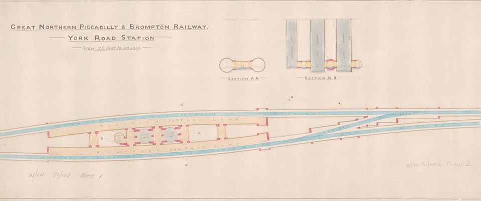
As promised, construction has begun on the York Road tube platforms baseboard. This photo shows the board just resting in front of the tube station: in its final form it will be below and centred on the lift shafts.
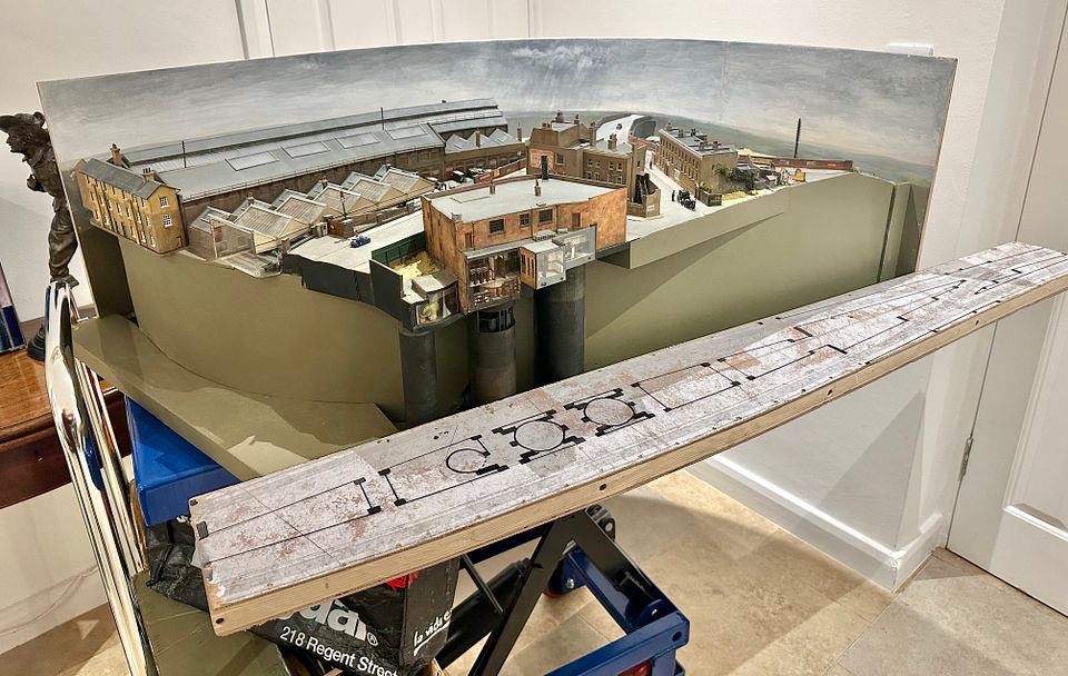
The prototype track plan (courtesy LT Museum) was printed to size and stuck to some 4mm ply. This was then tried for position on the main layout and fixing hole positions determined.
The ply top was then framed with 12x21mm pine strip wood screwed & glued in place. An oak block was incorporated at the end where the next board joins on: decent wood is essential for holding baseboard joiners in a repeatable position.
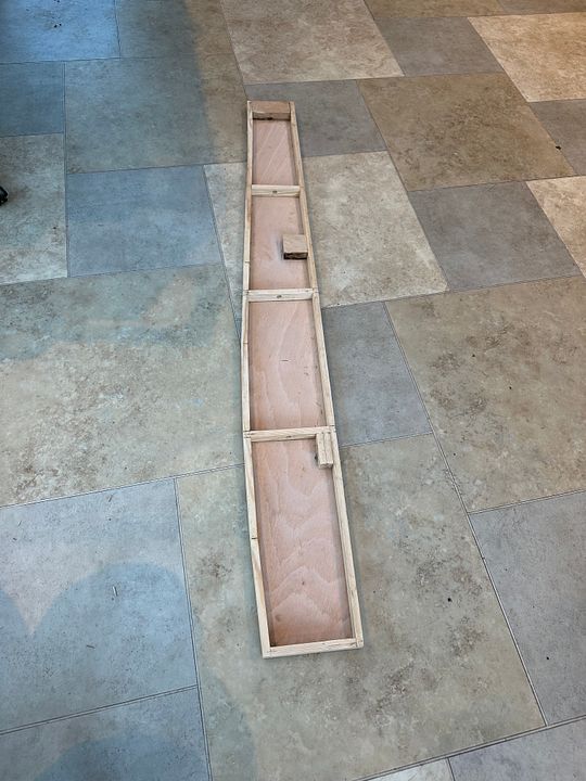
This was left overnight for the glue to set and then a lower skin of 4mm ply screwed and glued onto the pine wood frame. This I beam and stressed skin design makes the whole construction immensely rigid and pretty lightweight.
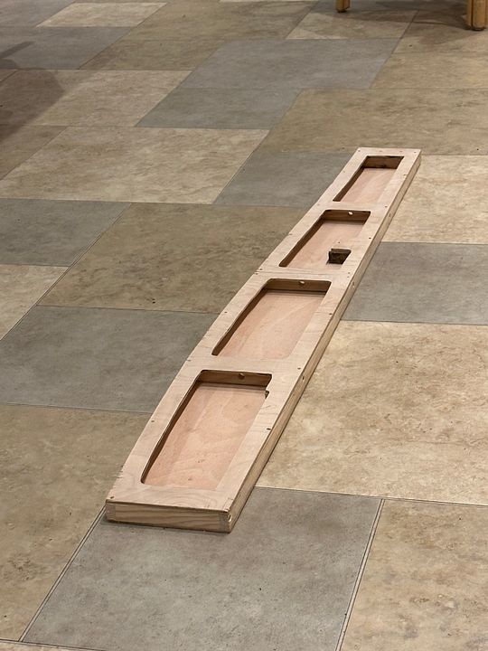
The track base will be 46mm below the underside of the layout with a spacing rib 75mm deep fixed to the back edge. Quite interesting really that this is the penultimate baseboard to be built for CF.
The planning of the station platform itself is well advanced with laser cut ribs and completely accurate tile artwork already for fitting.
Tim
The prototype track plan (courtesy LT Museum) was printed to size and stuck to some 4mm ply. This was then tried for position on the main layout and fixing hole positions determined.
The ply top was then framed with 12x21mm pine strip wood screwed & glued in place. An oak block was incorporated at the end where the next board joins on: decent wood is essential for holding baseboard joiners in a repeatable position.
This was left overnight for the glue to set and then a lower skin of 4mm ply screwed and glued onto the pine wood frame. This I beam and stressed skin design makes the whole construction immensely rigid and pretty lightweight.
The track base will be 46mm below the underside of the layout with a spacing rib 75mm deep fixed to the back edge. Quite interesting really that this is the penultimate baseboard to be built for CF.
The planning of the station platform itself is well advanced with laser cut ribs and completely accurate tile artwork already for fitting.
Tim