The GNR N2 failed to proceed on Copenhagen Fields at the Fareham show last weekend. It was made by the great Denys Brownlee and has run for 30 years, probably covering many hundred of real miles in that time.
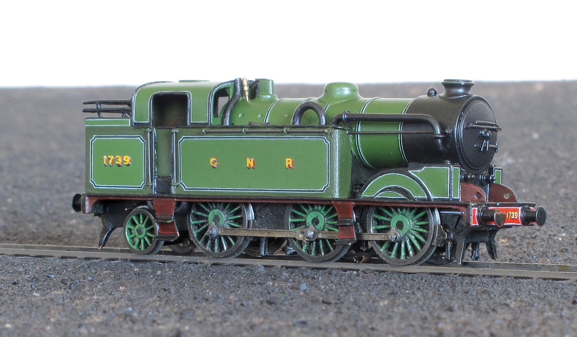
It is very rare for me to have two engines on the go at once, but I thought this deserved a ‘12 hour chassis’ - so it jumped the queue.
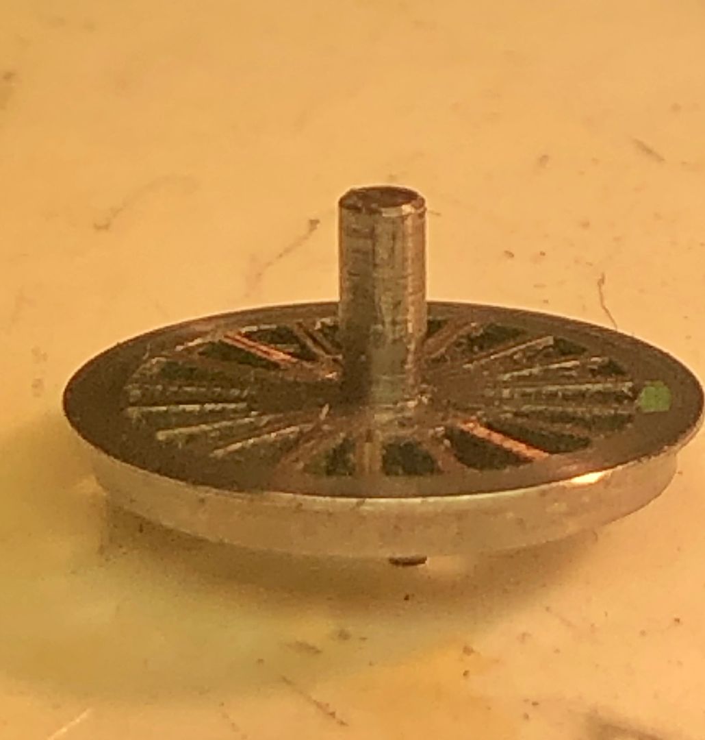
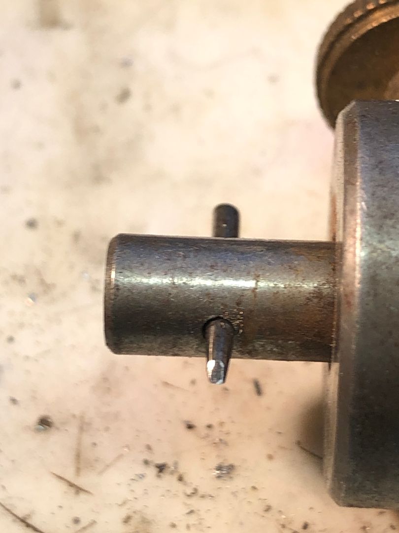
On examination, I found that the 1/16” axles were worn by 0.1mm.
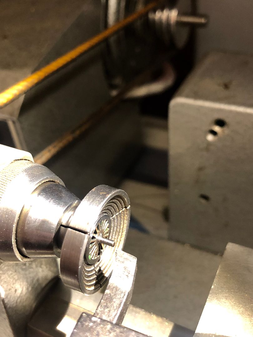
They were put in a step collet and have been re-profiled to 1.5 mm diameter.
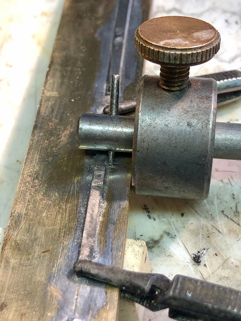
On looking closer I also noted significant wear on the coupling rod pins. Denys had used remarkably thin (for him) steel for the rods and it had ‘cut in’.
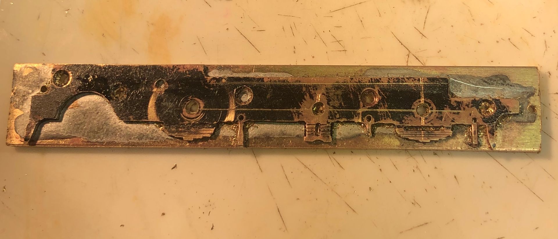
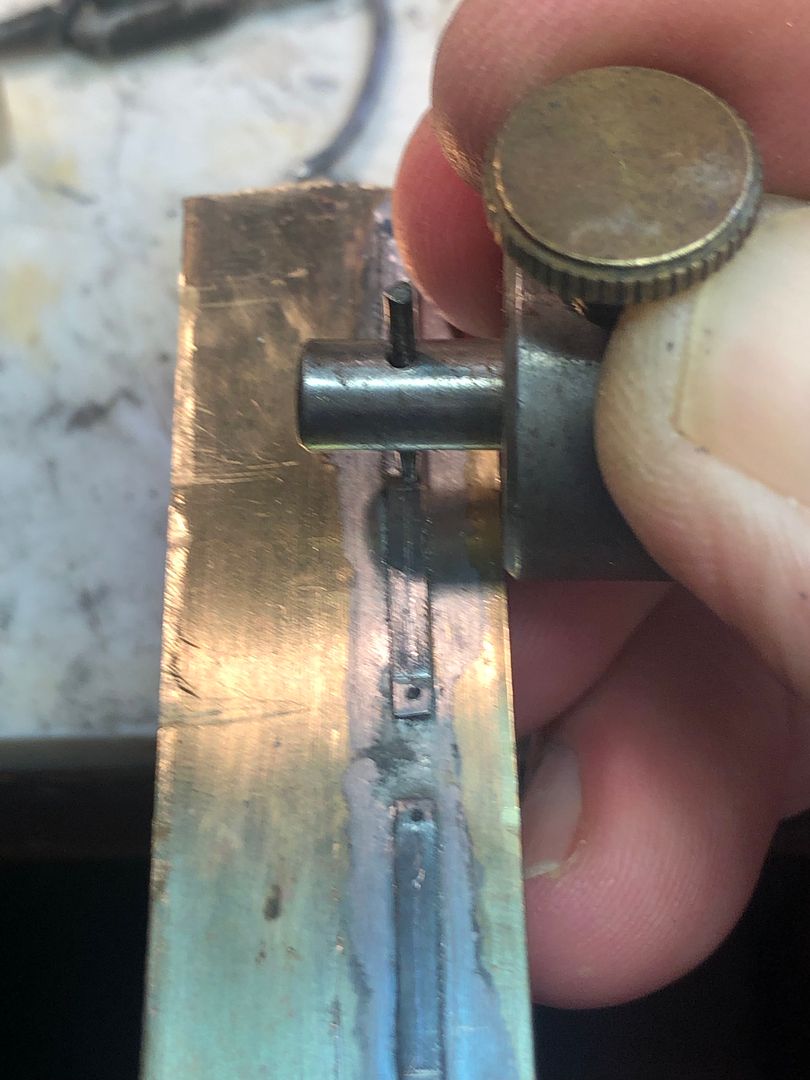
The original chassis has been made with brass frames and tapped acetal spacer blocks. The frames were separated from the blocks and one was sweated to two pieces of brass to act as a pattern for the replacement chassis.
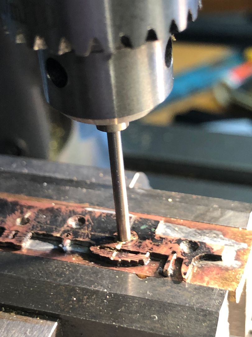
The old holes were located using an equivalent size drill upside down as a plug fit in the drill press, with the frames held accurately in a vice on the X - Y table of my mill - drill. Once the location was correct, the drill was used correct way up to make the hole. The axle holes were drilled by dead reckoning, using the table to set the coupled wheelbase.
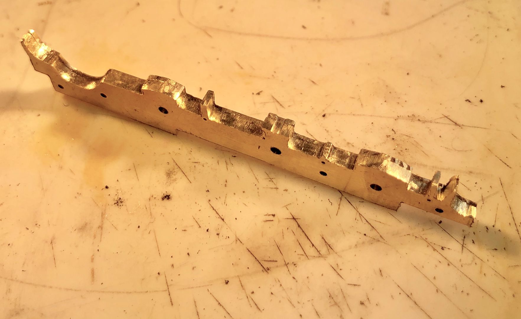
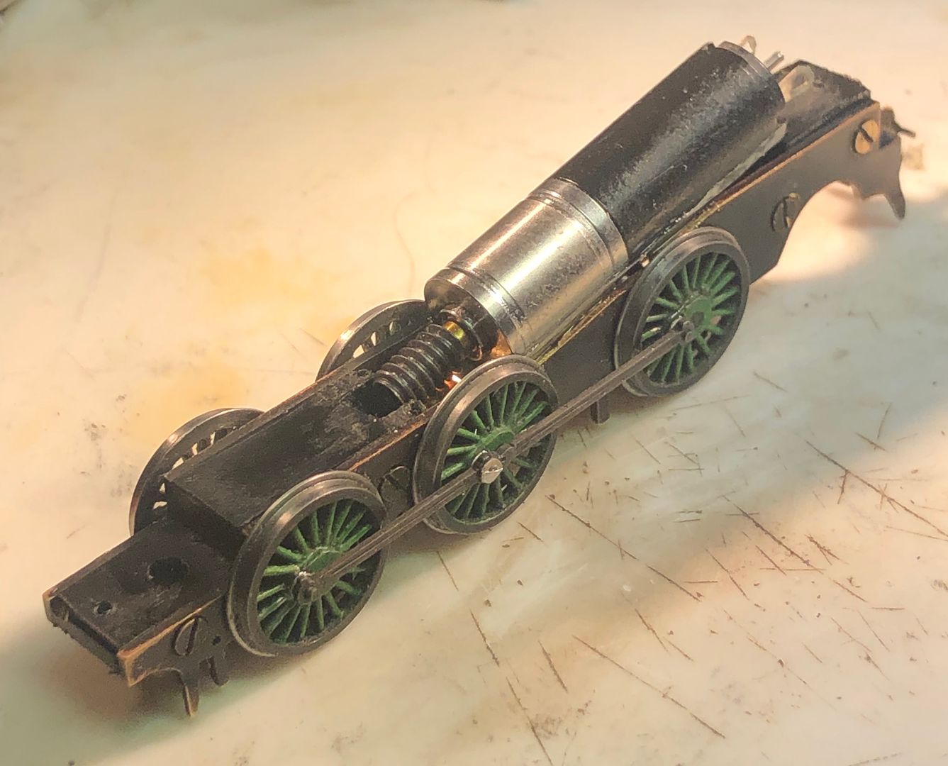
Once all the holes were made, the new chassis was filed up to shape using the old one as a pattern: the image shows the three pieces still sweated together.
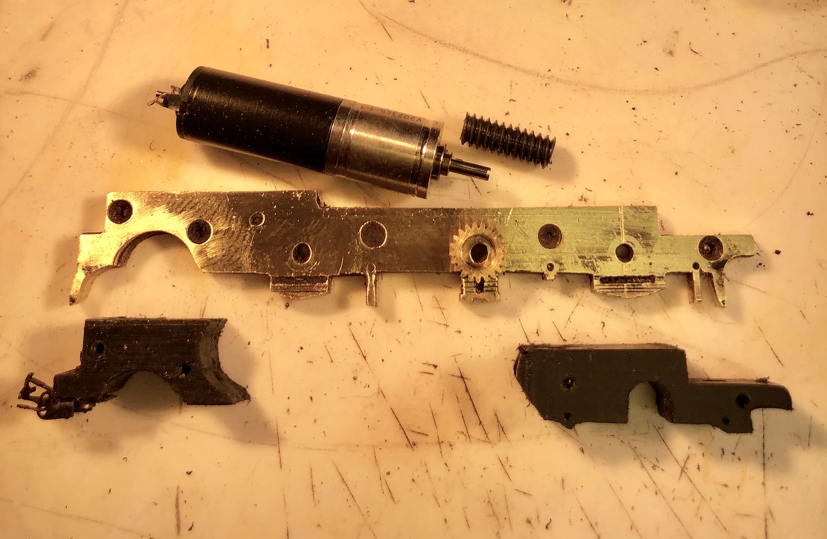
I was able to use quite a lot of Denys’ original chassis components, although the drive system will be quite different, with a Maxon motor and 1:4 gearbox driving onto a 21:1 worm & worm wheel.
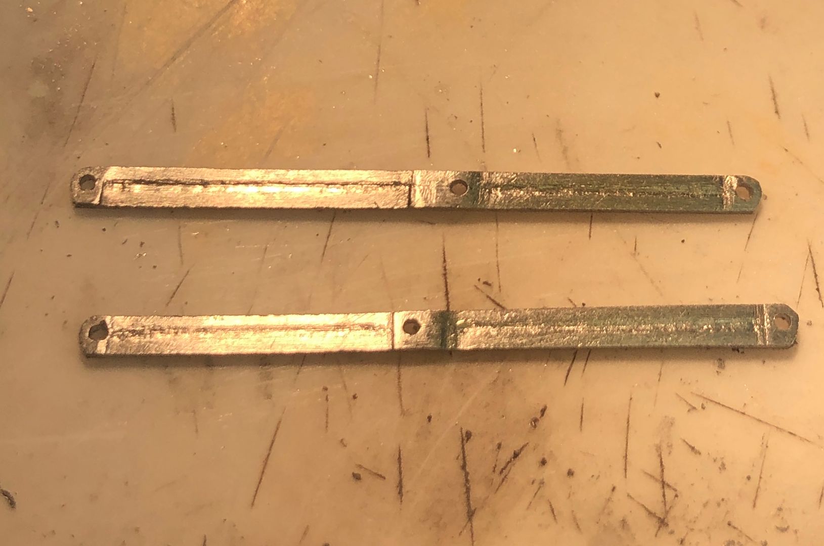
The coupling rods were made from two quite thick steel blanks sweated together with the holes again drilled by dead reckoning in the mill / drill. These were soldered to a 1/2” x 1/6” thick steel strip, taking care to make sure that they were parallel with one edge. This was achieved by tinning the components, holding them in place with some clips and then using a miniature marking gauge to nudge them parallel with the edge. A quick flash with the blow torch and liquid flux melted the solder to attach them to the brass.
The area between the bearings was thinned down using the brass strip to hold the rods in the vice and then draw filed to make a flat surface. The raised bearing areas help to stop the fluting extending.
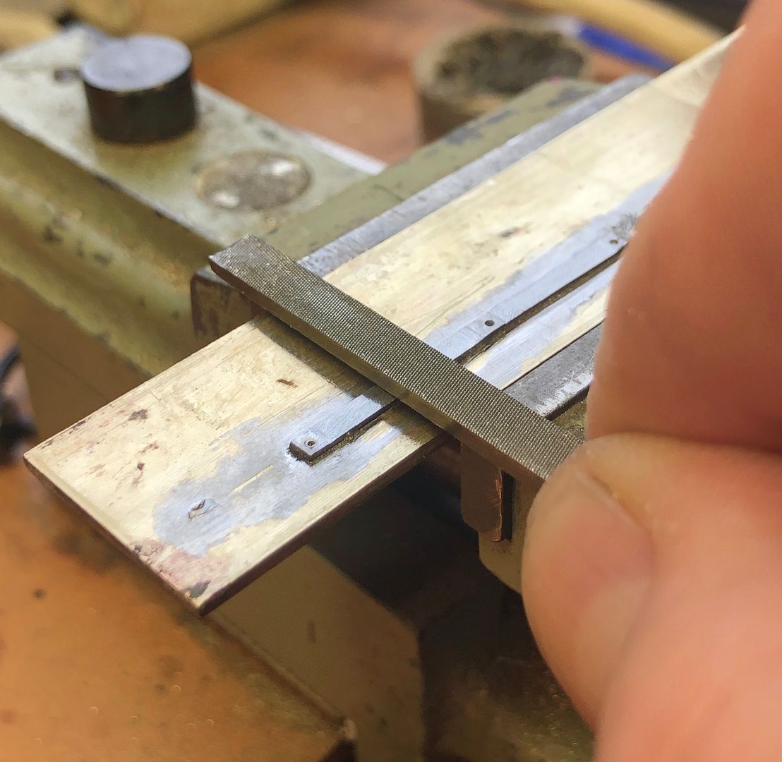
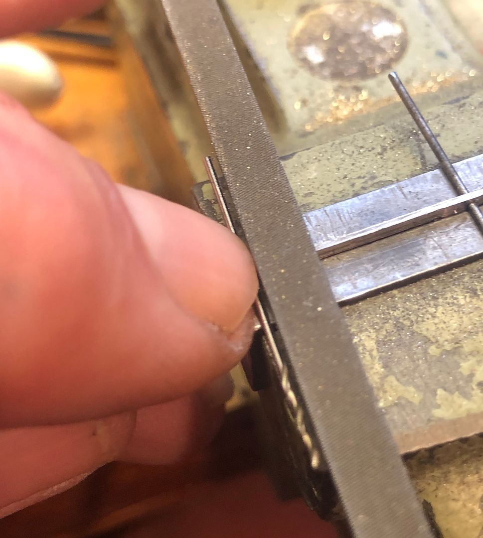
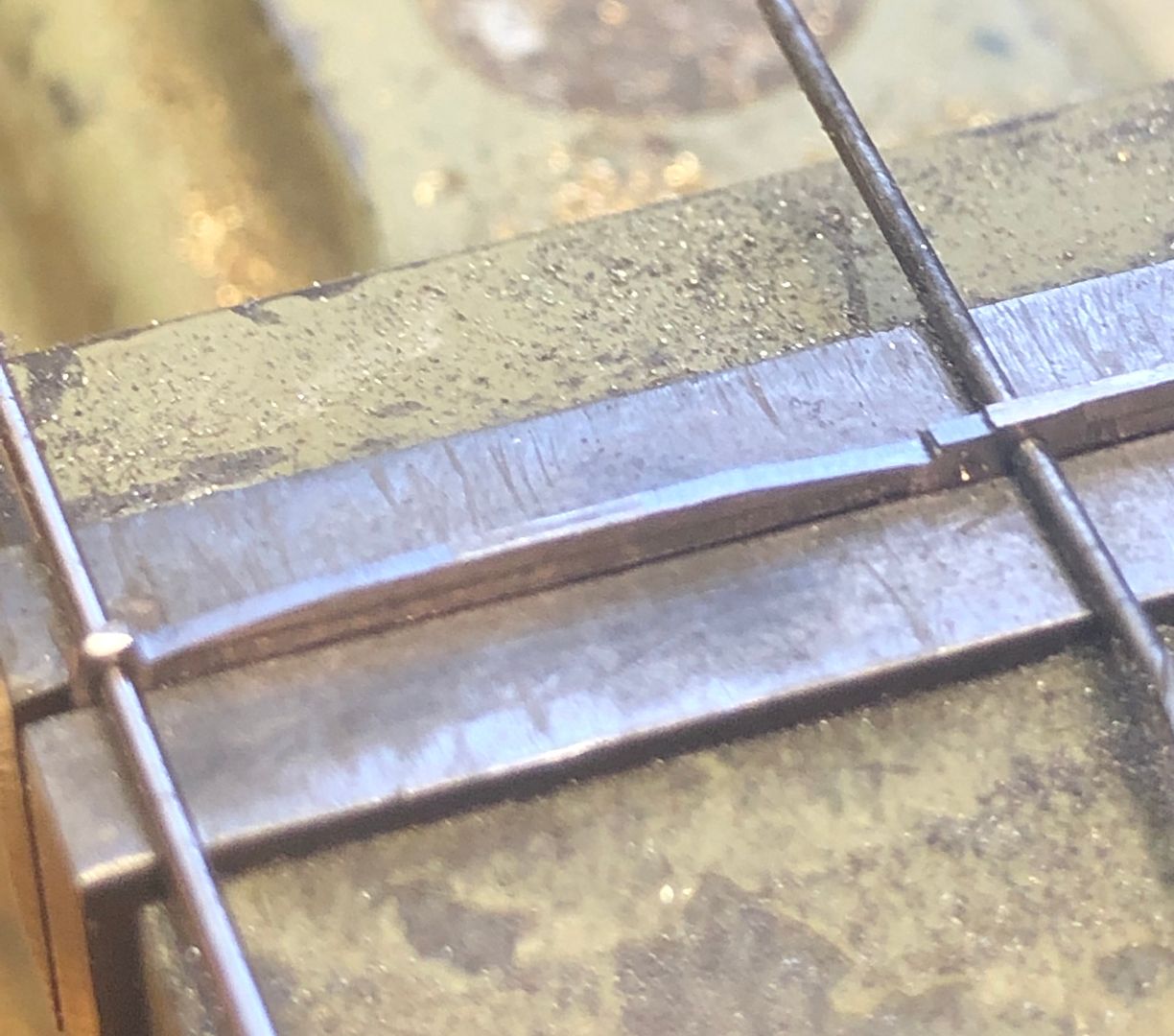
The flutes were made by using the same marking gauge, with a gramophone needle tip ground to a chisel shape for planing out the flute in the rods (which may have been how the originals were made).
Once this was completed, the brass was reheated with the blow torch and the two, very wide, coupling rods removed.
These were then reduced in height using drills through the rod holes to locate them in the vice. I use my fingernail to act as a stop, against which the safe edge of the file will run, when filing the areas that are difficult to see
A ‘stop’ is filed into the steel and then the material in the middle can be easily removed, finishing off with draw filing.
Final finishing includes filing in the oil caps and rounding off a few corners.
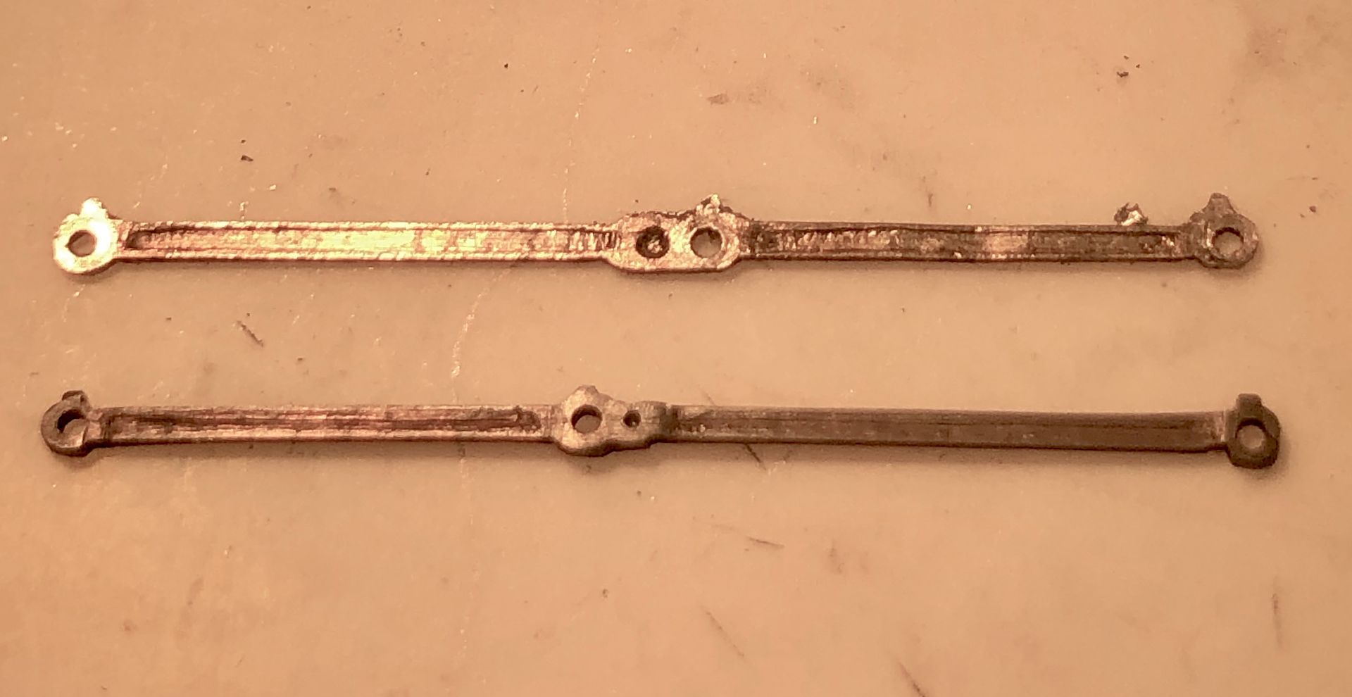
The rods are a bit smaller than Denys’ ones, but the bearing surface is greater. Steel is also much stronger than nickel silver when making valve gear.
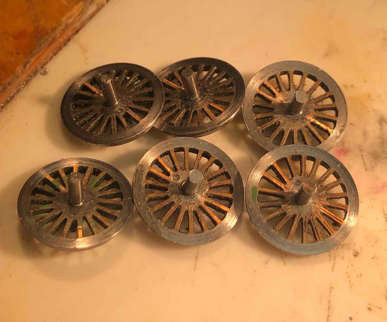
The chassis was assembled, wheels quartered and after a few minor tweaks of the coupling rods it was sufficiently free turning to bond the motor gear box to the Tri-ang type cut outs in the frames with 24 hr epoxy adhesive. The worm simply rests lightly on the worm wheel whilst the adhesive is curing. The motor casing had some insulating fag paper and 24hr epoxy wrapped onto the area that would be next to the frames, well ahead of final fixing to the chassis.
It may seem sloppy practice to glue a motor in place, but there is no maintenance possible on the motor-gear box. If the worm wears then a sharp tap with a screw driver underneath will break the glue joint and the final drive gears can be replaced. We have used this approach on quite a few of the tank engines on CF. The engine hasn’t yet turned its wheels in anger with the new chassis (the adhesive is curing as I write this), but it should be alright. More to the point, we will have had a replacement chassis made within a week of failure: there will probably have been a bit more than 12hrs work to get this chassis running, but that was mainly due to the need to make some fluted coupling rods.
Tim


