The theory is that you need less for your layout when modelling in O so it isn't as expensive as it may seem. But the reality is it depends on where you get your pleasure. I get mine from building models rather than running them so it costs.....
Rob P's 7mm Loco Workbench - LNER 06 from MOK 8F
Moderators: 52D, Tom F, Rlangham, Atlantic 3279, Blink Bonny, Saint Johnstoun, richard
-
Robpulham

- LNER A4 4-6-2 'Streak'
- Posts: 1715
- Joined: Thu Mar 27, 2008 9:54 pm
- Location: Lower Wensleydale
- Contact:
Re: Rob P's 7mm Loco Workbench - Always something going on..
Hi BB,
The theory is that you need less for your layout when modelling in O so it isn't as expensive as it may seem. But the reality is it depends on where you get your pleasure. I get mine from building models rather than running them so it costs.....
The theory is that you need less for your layout when modelling in O so it isn't as expensive as it may seem. But the reality is it depends on where you get your pleasure. I get mine from building models rather than running them so it costs.....
-
Blink Bonny

- LNER A4 4-6-2 'Streak'
- Posts: 3946
- Joined: Mon Dec 03, 2007 9:21 pm
- Location: The Midlands
- Contact:
Re: Rob P's 7mm Loco Workbench - Always something going on..
Ay up, Rob!
I also gain more pleasure from building than I do from running so a shift to the "senior scale" looks unlikely.
Sadly.
I also gain more pleasure from building than I do from running so a shift to the "senior scale" looks unlikely.
Sadly.
If I ain't here, I'm in Bilston, scoffing decent chips at last!!!!
-
Blink Bonny
- LNER A4 4-6-2 'Streak'
- Posts: 3946
- Joined: Mon Dec 03, 2007 9:21 pm
- Location: The Midlands
- Contact:
Re: Rob P's 7mm Loco Workbench - Always something going on..
Ay up, Rob!
I also gain more pleasure from building than I do from running so a shift to the "senior scale" looks unlikely.
Sadly.
I also gain more pleasure from building than I do from running so a shift to the "senior scale" looks unlikely.
Sadly.
If I ain't here, I'm in Bilston, scoffing decent chips at last!!!!
-
Robpulham
- LNER A4 4-6-2 'Streak'
- Posts: 1715
- Joined: Thu Mar 27, 2008 9:54 pm
- Location: Lower Wensleydale
- Contact:
Re: Rob P's 7mm Loco Workbench - Always something going on..
Although I have been quiet I have not been idle and the 06 moves slowly on.
The last few evenings and over the weekend have been spent on the cylinders/slidebars etc.
While it has taken time to get these sorted and the instructions do lack a little in places - I only discovered the cylinder backing pieces by accident while looking for something else.... it is a very enjoyable kit to build and I am learning all the way.
-
Robpulham
- LNER A4 4-6-2 'Streak'
- Posts: 1715
- Joined: Thu Mar 27, 2008 9:54 pm
- Location: Lower Wensleydale
- Contact:
Re: Rob P's 7mm Loco Workbench - Always something going on..
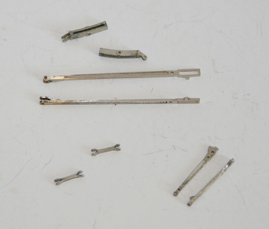
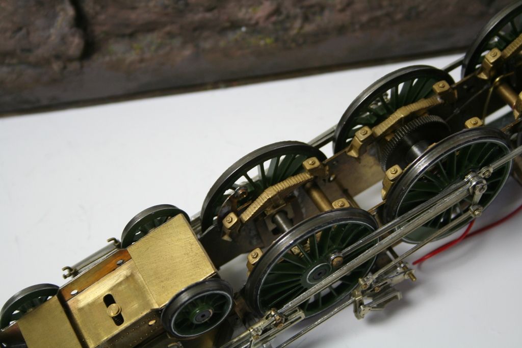
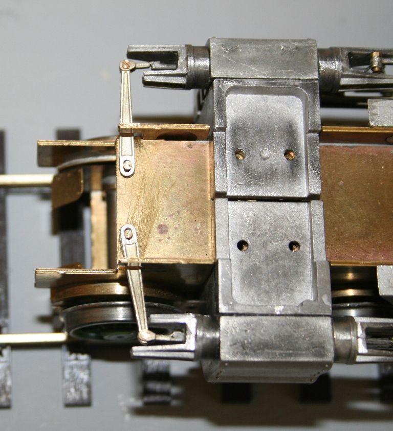
I haven't had much time recently so progress has been a bit intermittant. I have been working my way slowly through the valve gear and following Richard Lambert's example on another forum (not as nice as his efforts though). I have modified some of the bits so that they are a bit more prototypical. I am using the combination of the best bits from the kit and the premier rods. The mods are creating a fork on the ends of radius rod (Premier), creating the forked ends on the union links (MOK)
I didn't have any scale hardware nut heads of the right size (and funds are a little tight at the moment) so I made do with just putting a piece of scrap etch in the bottom of the expansion link.
Its probably not that visible in the photo but as Richard had to move the oiler from the side to the front on his cast combination lever. Mine being etched didn't have any at all. But a couple of pieces from some 2mm (I think but haven't measured) brass bar have done the trick (to the naked eye at any rate).
-
Robpulham
- LNER A4 4-6-2 'Streak'
- Posts: 1715
- Joined: Thu Mar 27, 2008 9:54 pm
- Location: Lower Wensleydale
- Contact:
Re: Rob P's 7mm Loco Workbench - Always something going on..
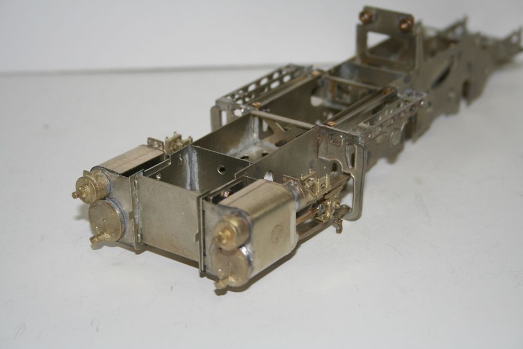
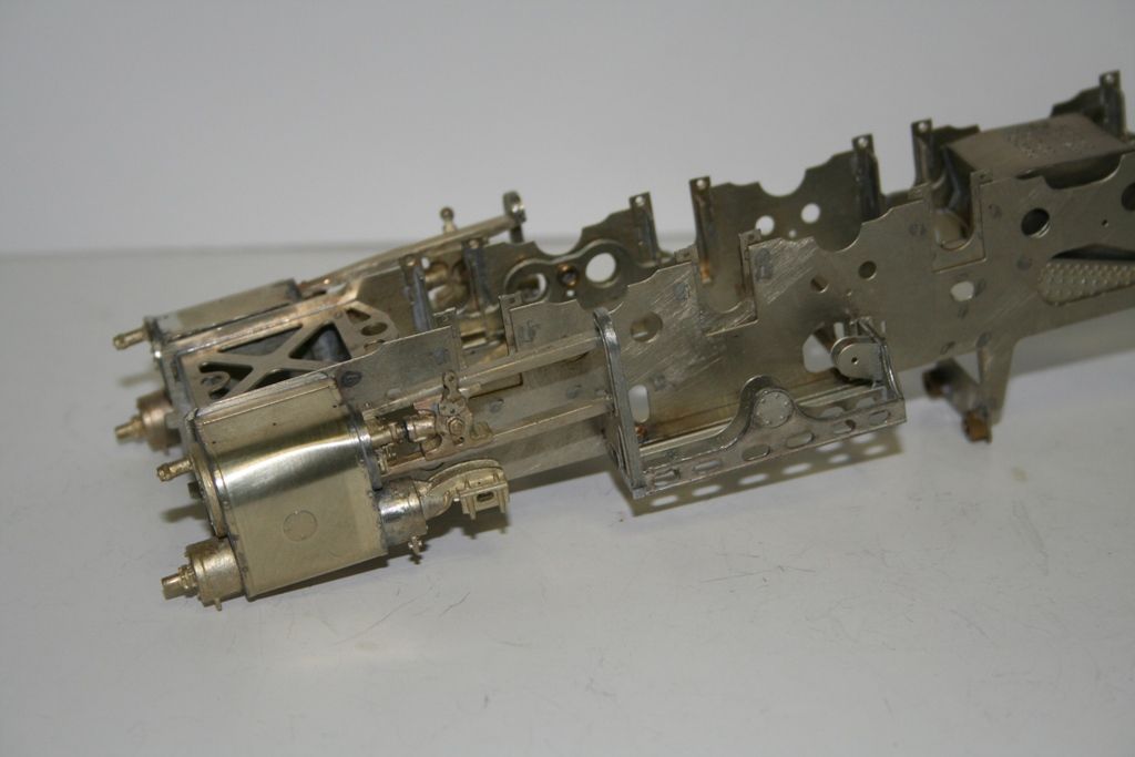
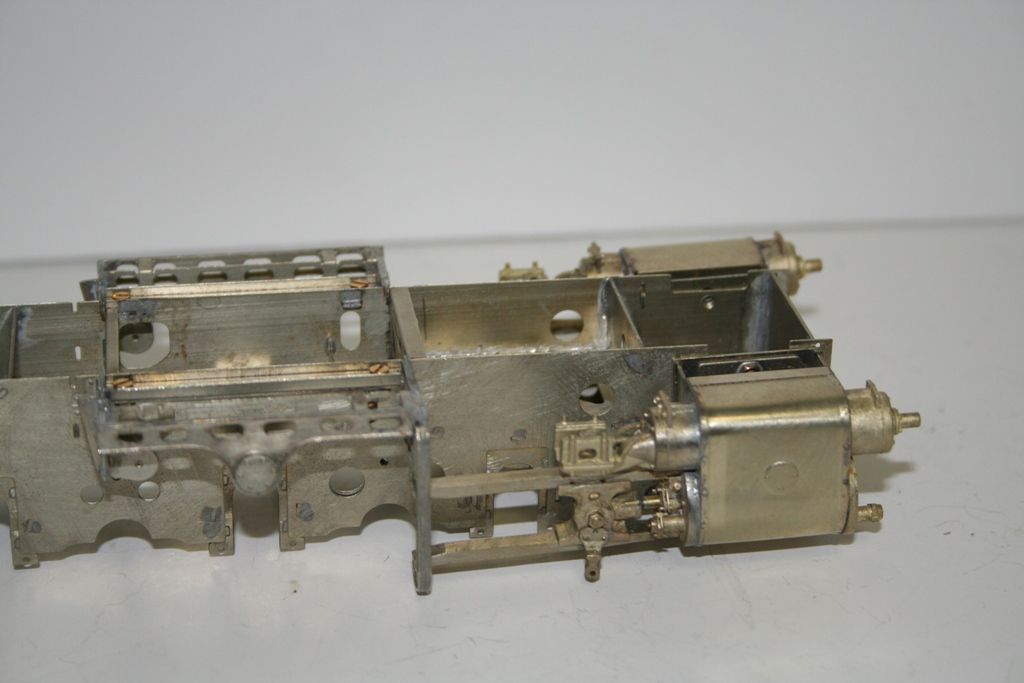
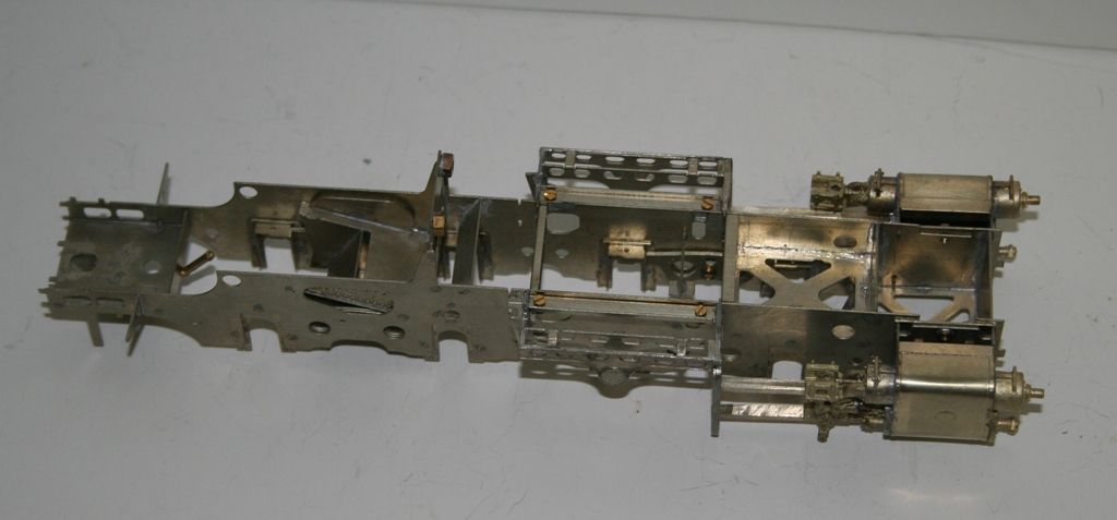
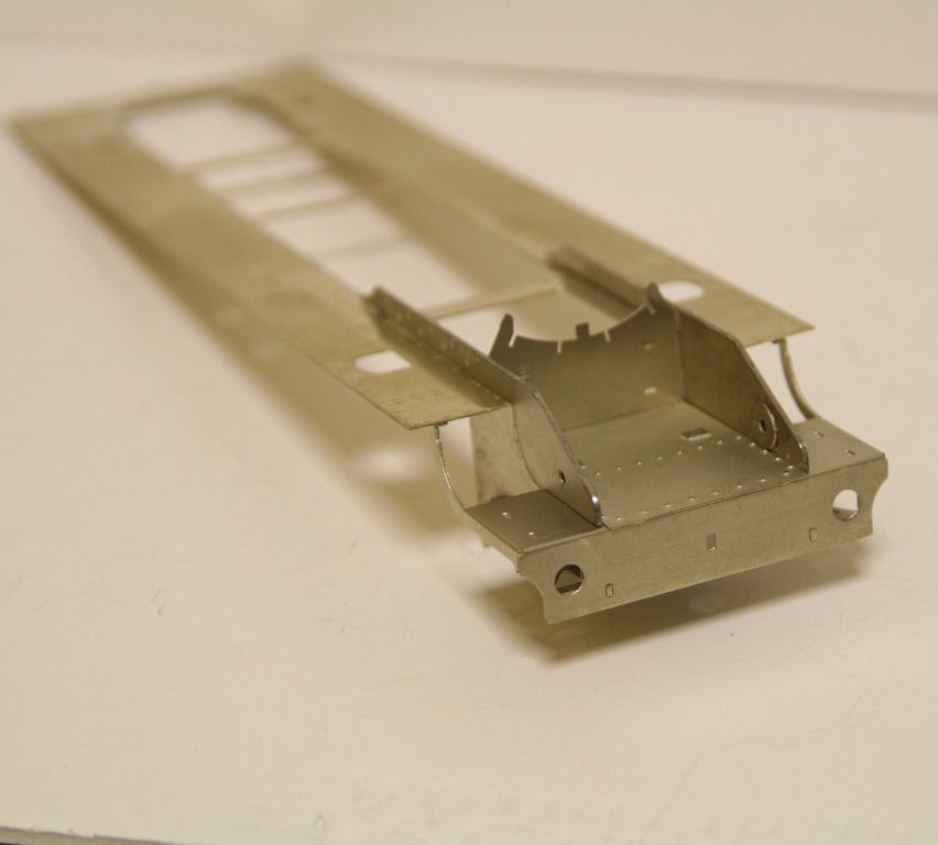
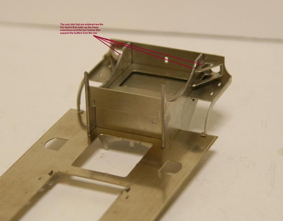
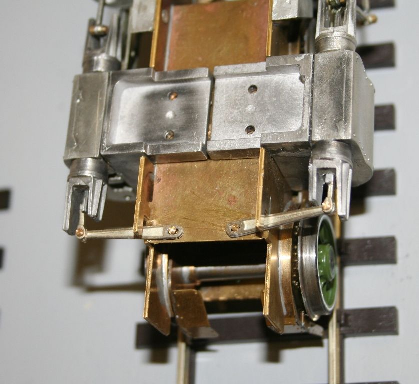
In between fiddling about with the valve gear I have also made up the front of the frames. At this point only the laminates of the frame extensions/lifting rings and the frames/cages that support the back of the buffers are soldered. All the rest is just held together with the slots and tabs. It really does make it easy when it all fits as it should and it is self supporting while you apply the solder.
-
manna

- LNER A4 4-6-2 'Streak'
- Posts: 3793
- Joined: Sun May 24, 2009 12:56 am
- Location: All over Australia
Re: Rob P's 7mm Loco Workbench - Always something going on..
G'Day Gents
Wonderful to watch a pile of bits of brass take shape, we could do with a envious icon !!
manna
Wonderful to watch a pile of bits of brass take shape, we could do with a envious icon !!
manna
EDGWARE GN, Steam in the Suburbs.
-
Robpulham
- LNER A4 4-6-2 'Streak'
- Posts: 1715
- Joined: Thu Mar 27, 2008 9:54 pm
- Location: Lower Wensleydale
- Contact:
Re: Rob P's 7mm Loco Workbench - Always something going on..
Cheers Manna, although it looks like brass in the photos (due to my poor lighting I suspect) the etches on this one are all nickel.manna wrote:G'Day Gents
Wonderful to watch a pile of bits of brass take shape, we could do with a envious icon !!
manna
-
Robpulham
- LNER A4 4-6-2 'Streak'
- Posts: 1715
- Joined: Thu Mar 27, 2008 9:54 pm
- Location: Lower Wensleydale
- Contact:
Re: Rob P's 7mm Loco Workbench - Always something going on..
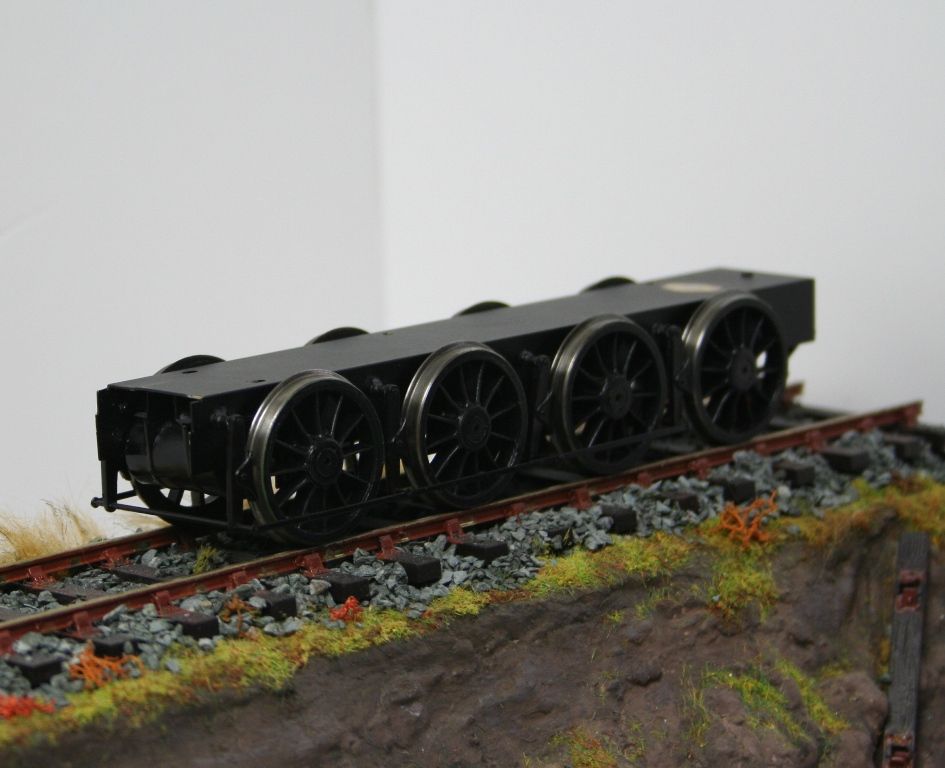
A couple of weeks ago in between finishing off the bogie van I got this out of the cupboard and started to think seriously about what needed doing to complete it. The first thing was fitting the front bogie I got it and the spring/screw and put it together and discovered the first problem. My lovely home made brake cylinders fouled the bogie and wouldn't allow it to turn at all - a proper Doh!!! moment. Undeterred I unsoldered them and started to cut them back in an effort to get them to sit further back. Several attempts later and there was nothing left
So here we are without any brakes but the chassis runs nice and smoothly and goes around curves as best as I can tell in the limits of my layout boards
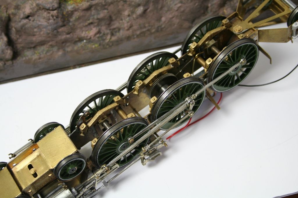
During the process one of the front springs can adrift at one side so that needs soldering back at some point.
The next problem that those with a long memory may recall was that when test running I had to rest a pair of pliers on one side of the tender to get it to run. My first thought was that this was down to a bad contact so I drilled a hole in the tender chassis, tapped it 8BA and soldered in a short length of screw (the end off one that I had shortened for something else - I struggle to throw stuff away thinking as now that they will come in useful). You can just see the mark on top of the tender chassis where I filed the paint off to do this.
I then reconnected the tender to the loco and all ran really smoothly. So far so good. however when I fitted the tender body it wouldn't run despite having a much better connection. It did run if I rested a finger on the tender side. Mmmm! I took the tender body off and examined it and realised that with the whitemetal castings that form the corridor connection top the body is top heavy at one side. Because I am using the american method of pick up the weight was lifting the chassis enough to make running intermittent.
My thoughts turned to how I could weight it from the inside of the tender body because any weight put into the tender top under the coal would be central not to one side that I needed.
I then thought about swapping the pick up sides on the loco and tender which would mean that the tender picked up from the side with the most weight and in theory it should solve the problem.
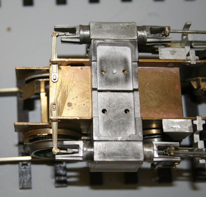
While all this was going through my mind I took the tender body back off and pondered while running the loco and tender chassis up and down my 4 metres of track. I noticed that the rear most wheels didn't always turn so I applied some oil to all the axles and running improved. It was while messing with this that I noticed that without the body on although the tender chassis ran up and down quite smoothly and appeared to pick up okay there was a pronounced rock between the front and rear axles and it was biased away from the pick up side. Closer examination revealed a bent bit of the chassis that looks like it has been dropped. I don't recall dropping it but I must have because no one else touches them.
This is it after a bit of minor straightening with a pair of sooth jawed pliers.
While the tweaking with the pliers hasn't solved the rocking it has made the rear axle run smoothly. So the next task is to strip down the tender chassis and attempt to straighten it. I will try initially without stripping any paint but if that fails it's going to be a back to basics job as I am now determined to get this of the bench once and for all so I can with other things without feeling guilty that it still lurks in the background.
So here we are without any brakes but the chassis runs nice and smoothly and goes around curves as best as I can tell in the limits of my layout boards


During the process one of the front springs can adrift at one side so that needs soldering back at some point.
The next problem that those with a long memory may recall was that when test running I had to rest a pair of pliers on one side of the tender to get it to run. My first thought was that this was down to a bad contact so I drilled a hole in the tender chassis, tapped it 8BA and soldered in a short length of screw (the end off one that I had shortened for something else - I struggle to throw stuff away thinking as now that they will come in useful). You can just see the mark on top of the tender chassis where I filed the paint off to do this.
I then reconnected the tender to the loco and all ran really smoothly. So far so good. however when I fitted the tender body it wouldn't run despite having a much better connection. It did run if I rested a finger on the tender side. Mmmm! I took the tender body off and examined it and realised that with the whitemetal castings that form the corridor connection top the body is top heavy at one side. Because I am using the american method of pick up the weight was lifting the chassis enough to make running intermittent.
My thoughts turned to how I could weight it from the inside of the tender body because any weight put into the tender top under the coal would be central not to one side that I needed.
I then thought about swapping the pick up sides on the loco and tender which would mean that the tender picked up from the side with the most weight and in theory it should solve the problem.
While all this was going through my mind I took the tender body back off and pondered while running the loco and tender chassis up and down my 4 metres of track. I noticed that the rear most wheels didn't always turn so I applied some oil to all the axles and running improved. It was while messing with this that I noticed that without the body on although the tender chassis ran up and down quite smoothly and appeared to pick up okay there was a pronounced rock between the front and rear axles and it was biased away from the pick up side. Closer examination revealed a bent bit of the chassis that looks like it has been dropped. I don't recall dropping it but I must have because no one else touches them.
This is it after a bit of minor straightening with a pair of sooth jawed pliers.


While the tweaking with the pliers hasn't solved the rocking it has made the rear axle run smoothly. So the next task is to strip down the tender chassis and attempt to straighten it. I will try initially without stripping any paint but if that fails it's going to be a back to basics job as I am now determined to get this of the bench once and for all so I can with other things without feeling guilty that it still lurks in the background.
-
Robpulham
- LNER A4 4-6-2 'Streak'
- Posts: 1715
- Joined: Thu Mar 27, 2008 9:54 pm
- Location: Lower Wensleydale
- Contact:
Re: Rob P's 7mm Loco Workbench - The A3, Oh no not again...
Today's efforts have been very positive.
First I stripped the wheels and axles from the tender chassis and used a couple of 15" or so lengths of 3/16 round bar through the front and rear axle bushes to twist the chassis until it felt better.
I tried in the front and rear axles but it still didn't sit square on my pane of glass so a little more tweaking was in order. Once I was satisfied I tried the tender chassis behind the loco just with the front and rear axles fitted. All ran smoothly so I loosely fitted the tender top. Astonishingly it moved under it's own power without hiccup although the loco wheels did slip a bit. I popped a lump of lead sheet across the front of the frames to stop this during testing.
The next step was to fit the two middle axles and try again with the tender top loosely fitted. It ran even better.
Lastly I bit the bullet and fastened the tender top and on thankfully it seems that is one problem solved.
I was so elated that I took a video which I will post as soon as the camera battery charges.
Next up I tried the boiler/footplate on and discovered that it wouldn't fit over the Maxon motor. Out with the mini drill and a drum sander which made short work of it. I still need a little fine tuning then I hope to have her running with the boiler in place.
-
Robpulham
- LNER A4 4-6-2 'Streak'
- Posts: 1715
- Joined: Thu Mar 27, 2008 9:54 pm
- Location: Lower Wensleydale
- Contact:
Re: Rob P's 7mm Loco Workbench - The A3, Oh no not again...
This is the promised video of the chassis/tender improvements.
http://youtu.be/VBkA9yhnx98
Sorry about the dodgy soundtrack....
http://youtu.be/VBkA9yhnx98
Sorry about the dodgy soundtrack....
-
Robpulham
- LNER A4 4-6-2 'Streak'
- Posts: 1715
- Joined: Thu Mar 27, 2008 9:54 pm
- Location: Lower Wensleydale
- Contact:
Re: Rob P's 7mm Loco Workbench - The A3, Oh no not again...
Last night I couldn't resist putting the boiler and cab in place to get an idea how she would look and run when finished.
http://youtu.be/x8dIR0916N0
She sure looks like an A3 now
http://youtu.be/x8dIR0916N0
She sure looks like an A3 now
-
Robpulham
- LNER A4 4-6-2 'Streak'
- Posts: 1715
- Joined: Thu Mar 27, 2008 9:54 pm
- Location: Lower Wensleydale
- Contact:
Re: Rob P's 7mm Loco Workbench - The A3, Oh no not again...
Not much has been happening on the workbench of late due to DIY/Gardening and general lack of Mojo :0(
One of this things that has been done is one of those things that I was dreading and which when I finally plucked up the courage to have a go at it went very smoothly and easily.
What I was dreading was soldering the two pieces together in between the whitemetal fingers.
How I achieved it was:
I fastened both arms to the links to the rods together with the 16ba nut and bolt provided. The ends of each are half thickness to create a lap joint. I then bolted one end to the frame spacer and held the two half lapped ends together with a pair of cranked locking tweezers.
Next using a tip that I picked up on one of Richard Lambert’s threads I cut some strips of kitchen paper and folded them so that they would fit down either side of the area to be soldered and wet them with a pipette after using tweezers to position them. Once the whitemetal at both sides was suitably protected, flux was applied to the joint; a quick in and out with the soldering iron tinned with 145 degree solder and the job was done.
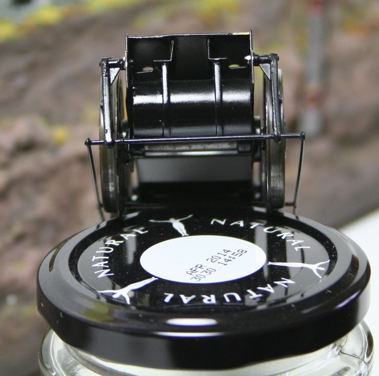
Hopefully the 3 photos show the various positions as the valve gear moves.
One of this things that has been done is one of those things that I was dreading and which when I finally plucked up the courage to have a go at it went very smoothly and easily.
What I was dreading was soldering the two pieces together in between the whitemetal fingers.
How I achieved it was:
I fastened both arms to the links to the rods together with the 16ba nut and bolt provided. The ends of each are half thickness to create a lap joint. I then bolted one end to the frame spacer and held the two half lapped ends together with a pair of cranked locking tweezers.
Next using a tip that I picked up on one of Richard Lambert’s threads I cut some strips of kitchen paper and folded them so that they would fit down either side of the area to be soldered and wet them with a pipette after using tweezers to position them. Once the whitemetal at both sides was suitably protected, flux was applied to the joint; a quick in and out with the soldering iron tinned with 145 degree solder and the job was done.
Hopefully the 3 photos show the various positions as the valve gear moves.
-
Atlantic 3279

- LNER A4 4-6-2 'Streak'
- Posts: 6537
- Joined: Fri Jun 26, 2009 9:51 am
- Location: 2850, 245
Re: Rob P's 7mm Loco Workbench - The A3, Oh no not again...
Lovely! Go on, you know you want to have a go at the complete 2:1 arrangement now......
Most subjects, models and techniques covered in this thread are now listed in various categories on page1
Dec. 2018: Almost all images that disappeared from my own thread following loss of free remote hosting are now restored.
Dec. 2018: Almost all images that disappeared from my own thread following loss of free remote hosting are now restored.
-
Robpulham
- LNER A4 4-6-2 'Streak'
- Posts: 1715
- Joined: Thu Mar 27, 2008 9:54 pm
- Location: Lower Wensleydale
- Contact:
Re: Rob P's 7mm Loco Workbench - The A3, Oh no not again...
Thanks Graeme, I think that I may get my chance - I believe that the Finney kits that I have in the stash (A4 and V2) both have rather more than DJH offer in this department.Atlantic 3279 wrote:Lovely! Go on, you know you want to have a go at the complete 2:1 arrangement now......