Copenhagen Fields & TFW’s workshop
Moderators: 52D, Tom F, Rlangham, Atlantic 3279, Blink Bonny, Saint Johnstoun, richard
Re: Copenhagen Fields & TFW’s workshop
The trouble is that 95% of the people looking at the layout will see the wonky buffer and think, "pah, what a load of rubbish. Can't even get the buffers straight".
-
Tim Watson
- GER D14 4-4-0 'Claud Hamilton'
- Posts: 310
- Joined: Mon Oct 24, 2016 11:37 am
Re: Copenhagen Fields & TFW’s workshop
Am I the only one that dislikes making tender & engine steps? I have made them up from the etches, but the tender ones were a bit tricky because there is a curve / angled area above the top step.
The etched top of the step was bent over and burnished to give a sharp bracket to solder to the tender body.
The tricky bit was that the change in angle occurs below that. There seems to be variations in the tenders as to how pronounced this is, but in the self trimming tender it seems quite subtle. Packing the top of the step above the vice and then bending over with a file, to exert an even pressure, produced a regular shape for all four steps.
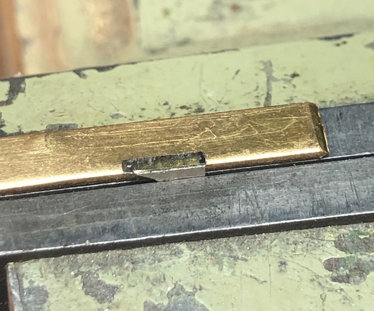
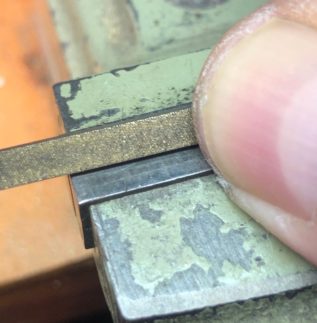
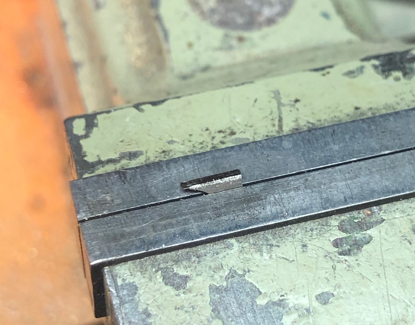
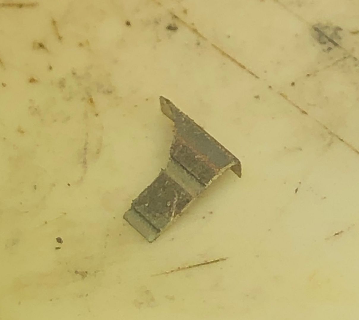
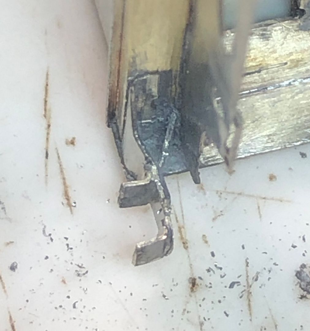
Soldering on the step bodies was straightforward. The steps themselves were etched in the kit, but at 8 thou thick are over-scale and jolly fiddly to handle. I therefore made new steps from 5 thou N/S strip. The end was bent up at 90 degrees to solder to the backing plate and then the rough size of the step weakened in the strip with a pair of side cutters.
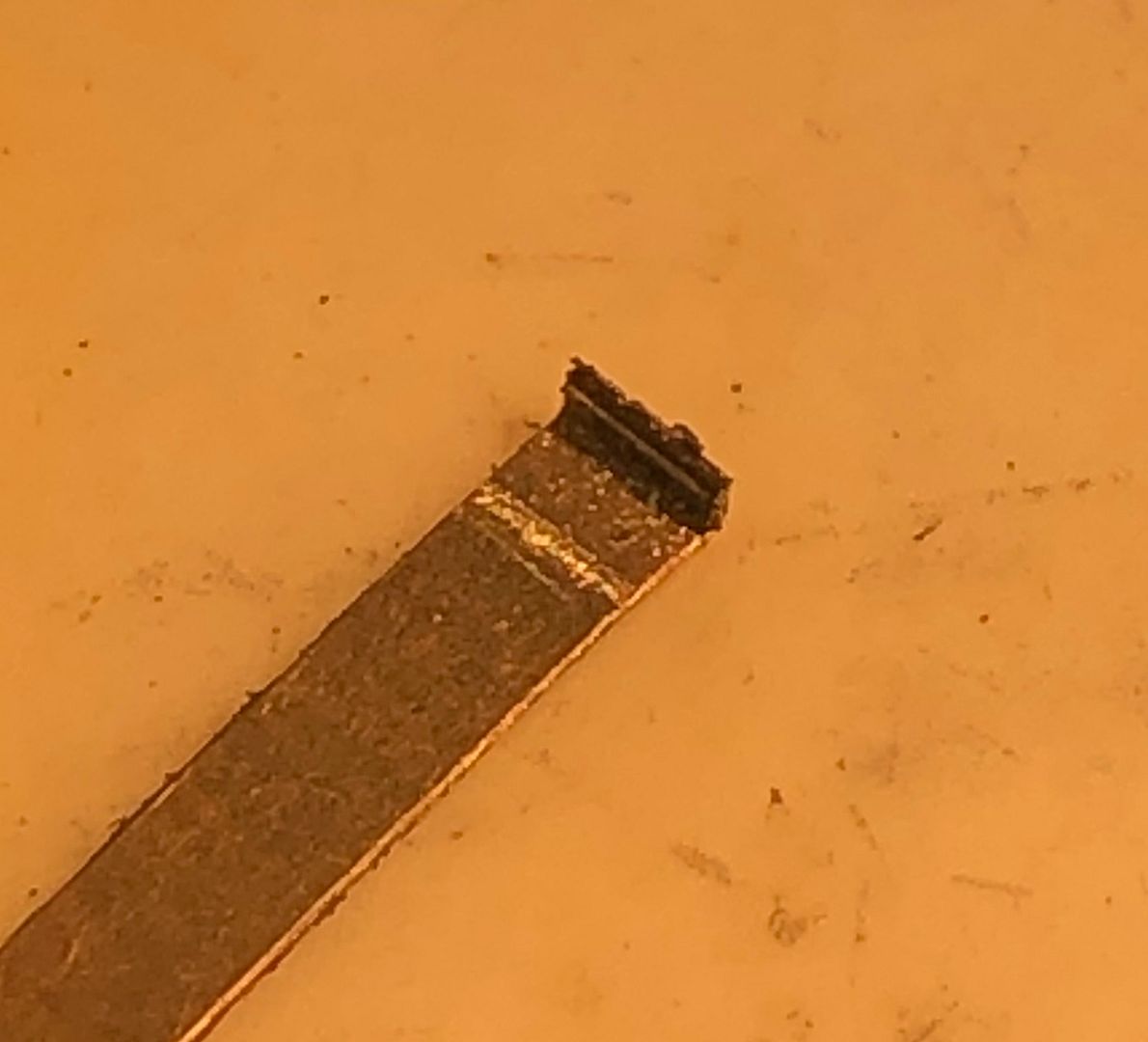
The long strip was then much easier to hold in place whilst the soldering iron was bought in to flash the tinned joint. After placement the fatigued/weakened area allows the holding piece to be snapped off the step.
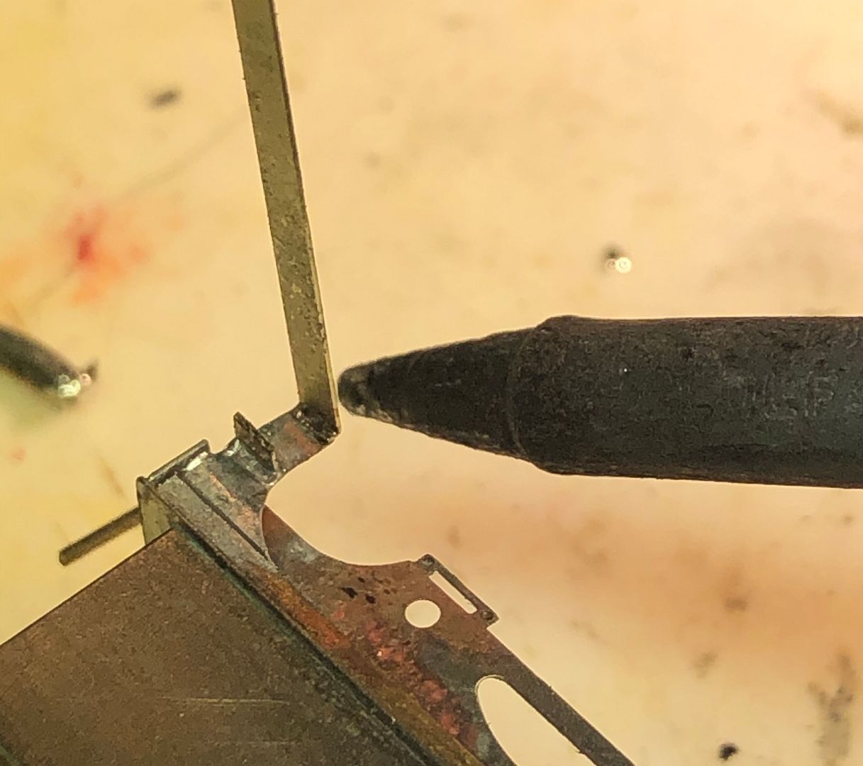
On the engine cab steps, the design is slightly different with a groove or slot to hold the steps and so the individual steps were soldered into place directly, being held by some titanium tweezers that will not take up soft solder.
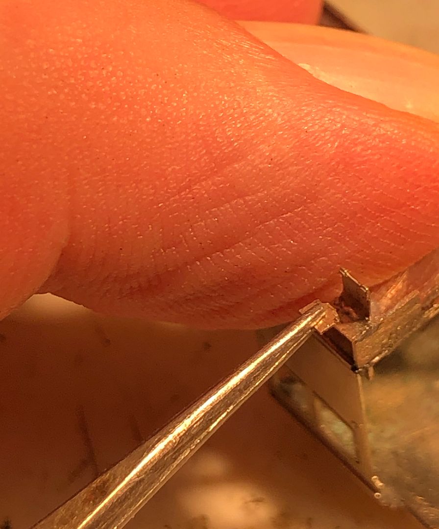
The half etched back plate for the steps produced a rather weak structure and so a bracing bracket was sweated in behind, which is also prototypical.
All OK in the end, but not my favourite job on an engine.
Tim

The etched top of the step was bent over and burnished to give a sharp bracket to solder to the tender body.
The tricky bit was that the change in angle occurs below that. There seems to be variations in the tenders as to how pronounced this is, but in the self trimming tender it seems quite subtle. Packing the top of the step above the vice and then bending over with a file, to exert an even pressure, produced a regular shape for all four steps.


Soldering on the step bodies was straightforward. The steps themselves were etched in the kit, but at 8 thou thick are over-scale and jolly fiddly to handle. I therefore made new steps from 5 thou N/S strip. The end was bent up at 90 degrees to solder to the backing plate and then the rough size of the step weakened in the strip with a pair of side cutters.

The long strip was then much easier to hold in place whilst the soldering iron was bought in to flash the tinned joint. After placement the fatigued/weakened area allows the holding piece to be snapped off the step.

On the engine cab steps, the design is slightly different with a groove or slot to hold the steps and so the individual steps were soldered into place directly, being held by some titanium tweezers that will not take up soft solder.

The half etched back plate for the steps produced a rather weak structure and so a bracing bracket was sweated in behind, which is also prototypical.

All OK in the end, but not my favourite job on an engine.

Tim
-
Tim Watson
- GER D14 4-4-0 'Claud Hamilton'
- Posts: 310
- Joined: Mon Oct 24, 2016 11:37 am
Re: Copenhagen Fields & TFW’s workshop
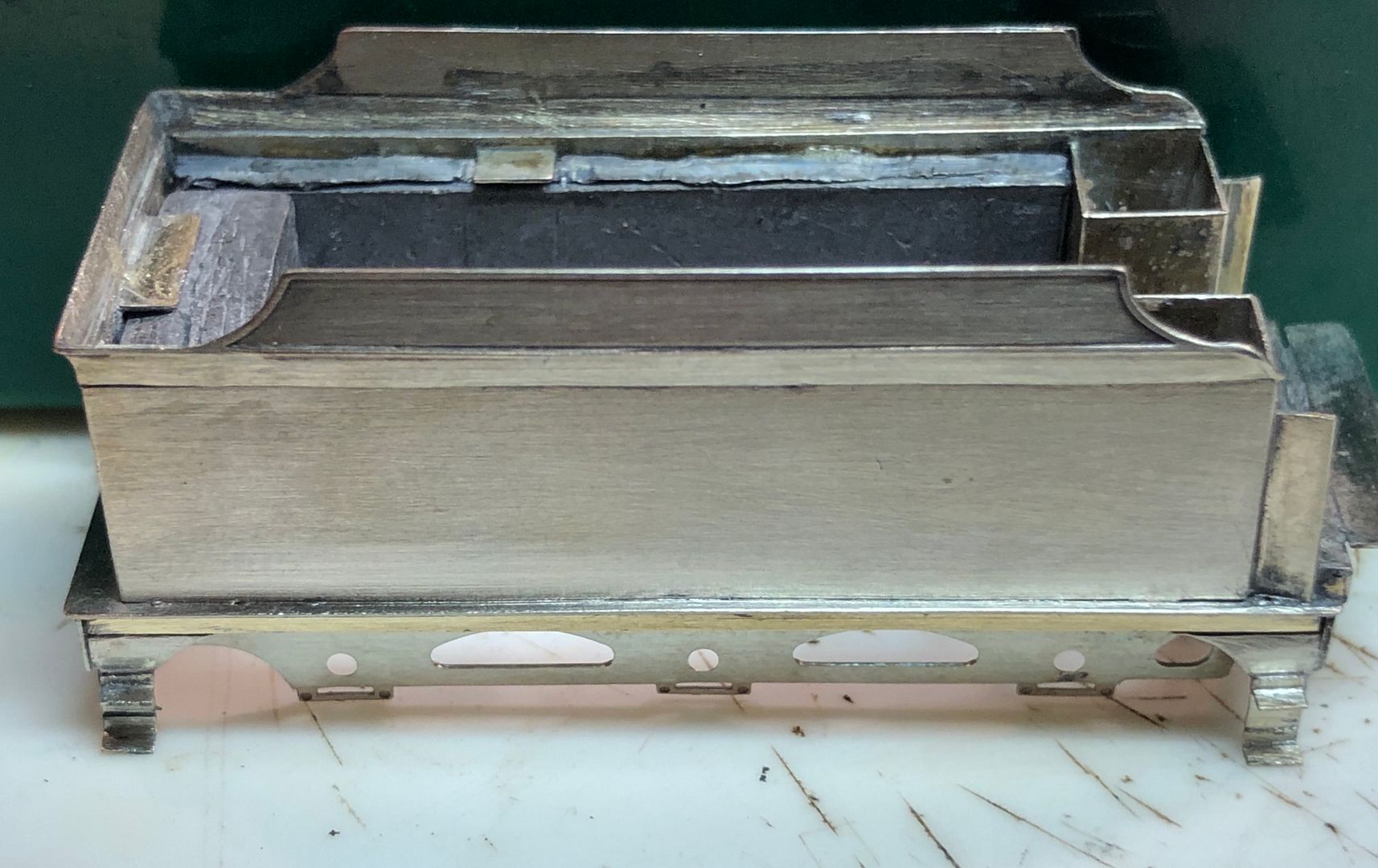
I couldn’t quite see what was wrong with the steps, but Tony Gee kindly put me wise to the problem. The middle step should be upside down, with the support bracket underneath, not above. That way it sits in next to the angled piece rather better. Thirty minutes work to make and fit some new steps (I’ve got my eye in on this step making lark).
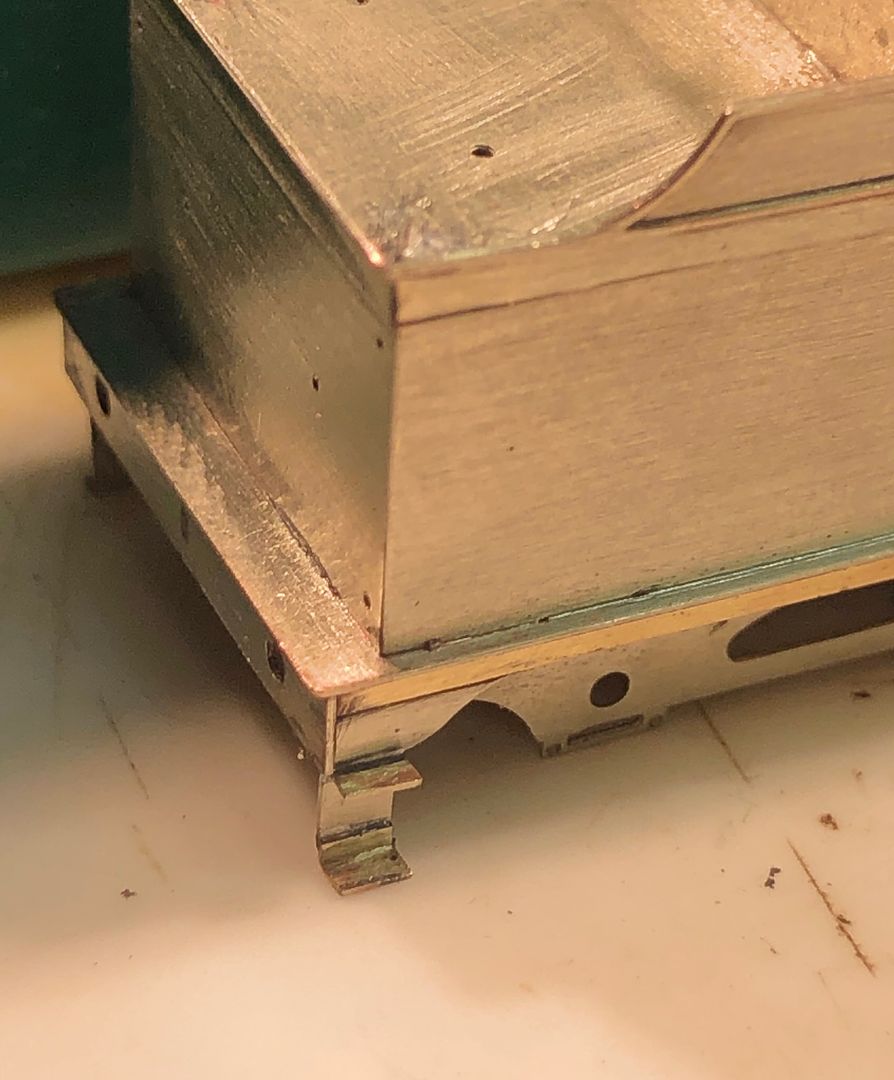
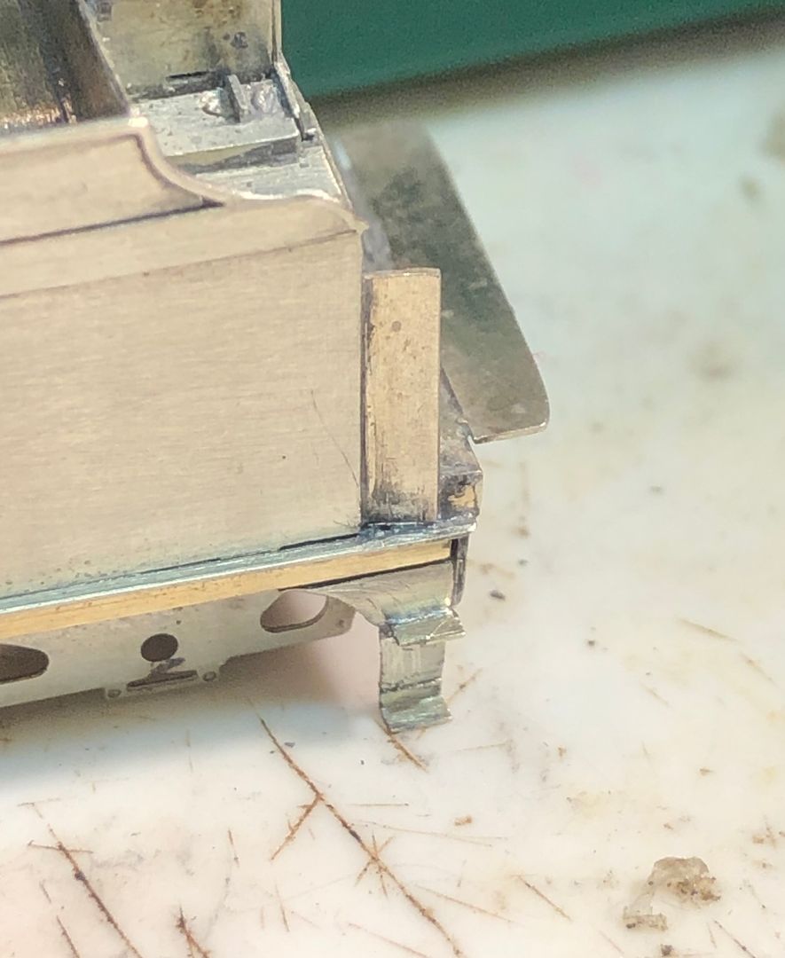
The steps are a little short of the buffer beam at the back because there is no side upstand.
Tim


The steps are a little short of the buffer beam at the back because there is no side upstand.
Tim
-
Tim Watson
- GER D14 4-4-0 'Claud Hamilton'
- Posts: 310
- Joined: Mon Oct 24, 2016 11:37 am
Re: Copenhagen Fields & TFW’s workshop
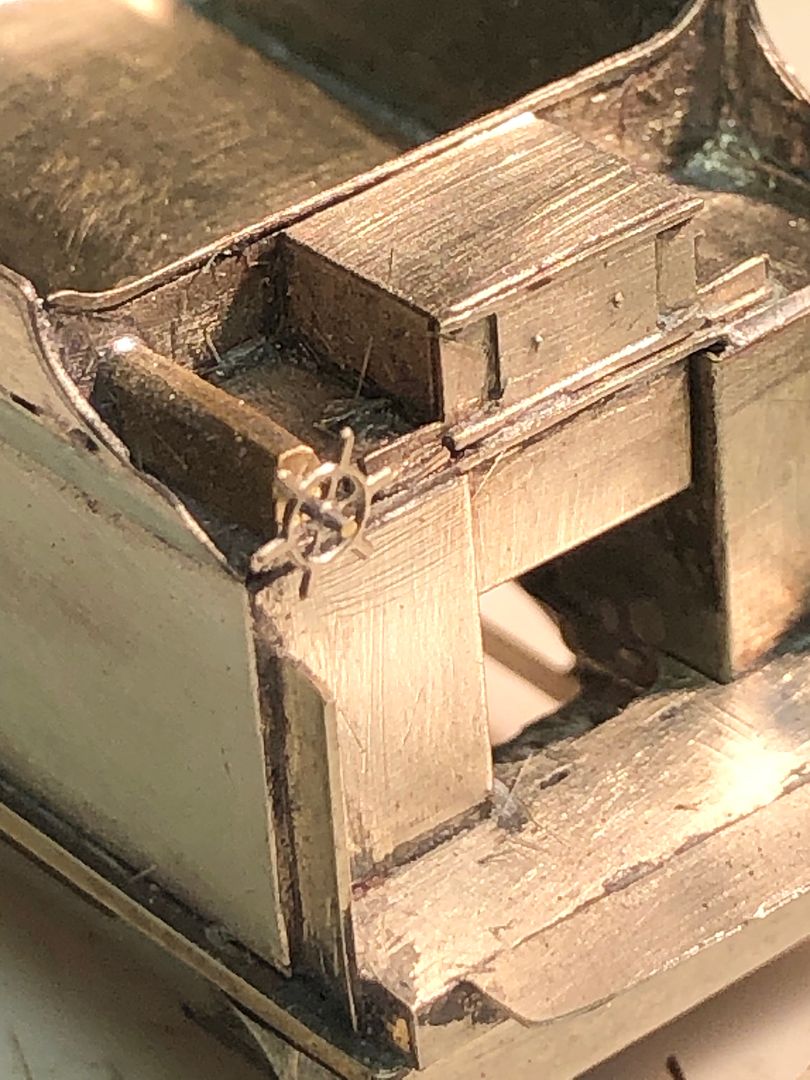
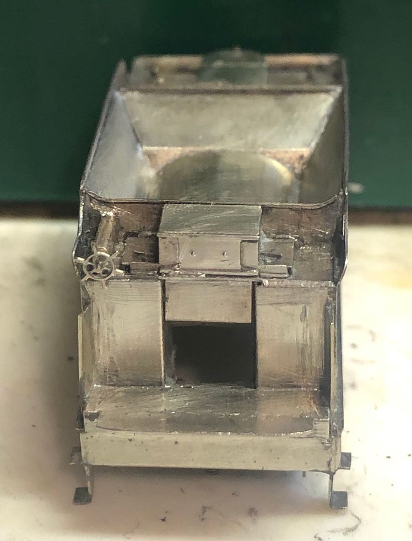
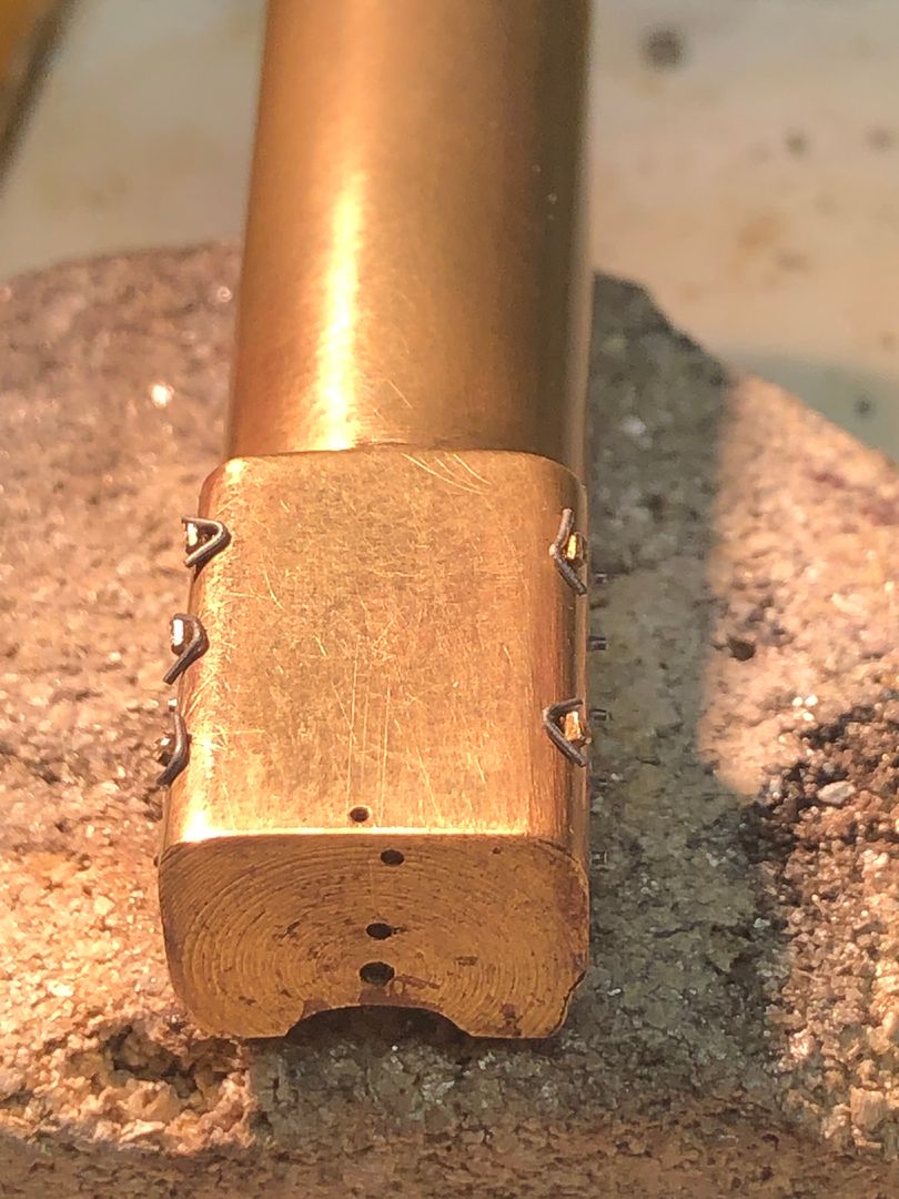
I was looking forward to making the tender filler and water scoop gear boxes for Valour and they didn’t take too long to put together. A few hacks into a lump of brass and some filing produced the quite complicated shape of the boxes and the rounded filler.
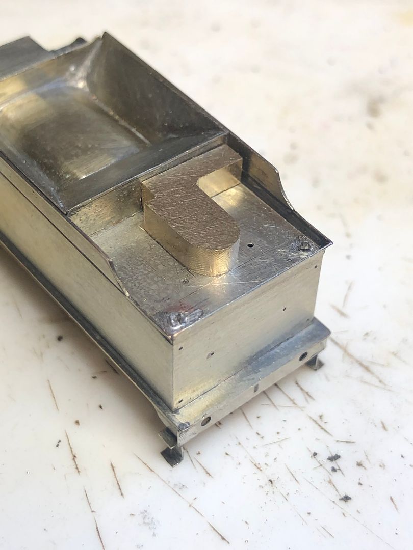
The lids were made by sweating the brass to some 5 thou N/S sheet and then filing this just about back to the brass, leaving a lip behind.
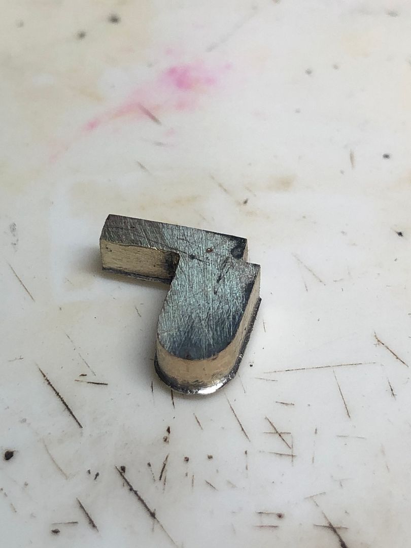
The hinges and joints were made by scribing the top with a scalpel. The handles were made by drilling a 0.3mm hole, soldering a short length of brass into it and then squeezing the round brass in the vice to flatten it. The shape of the handle was then filed into the remaining material.
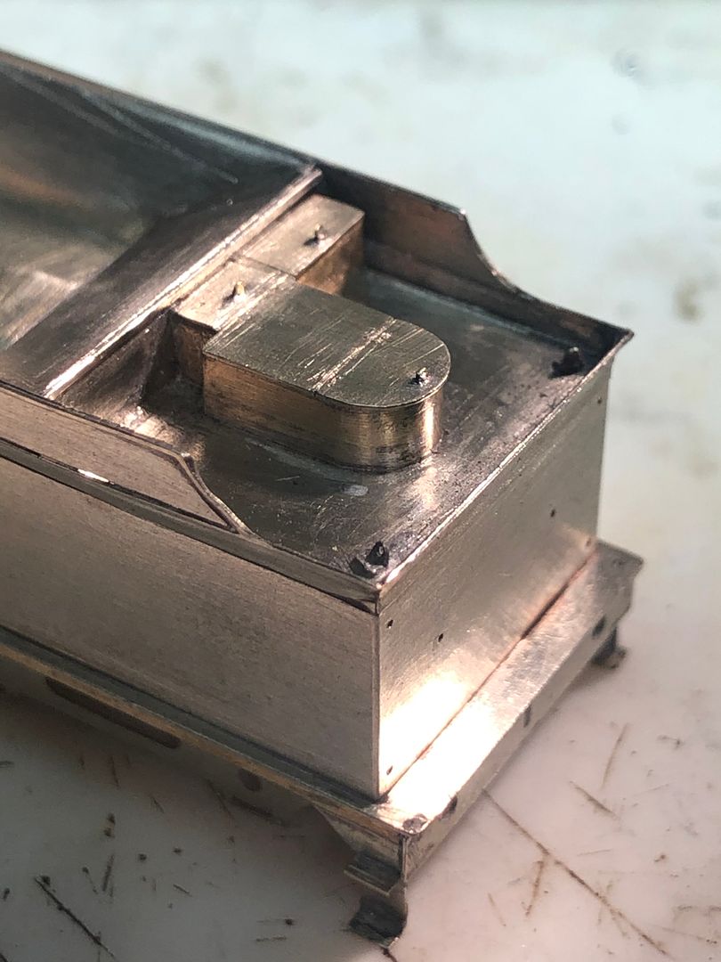
It all begins to make the tender look more businesslike.
Tim
-
Tim Watson
- GER D14 4-4-0 'Claud Hamilton'
- Posts: 310
- Joined: Mon Oct 24, 2016 11:37 am
Re: Copenhagen Fields & TFW’s workshop
The GC water scoop tenders had a cute little ships wheel to help raise & lower the scoop. This tender etch doesn’t have any included, but I was fortunately given one from a Michael Edge etch for a standard tender.
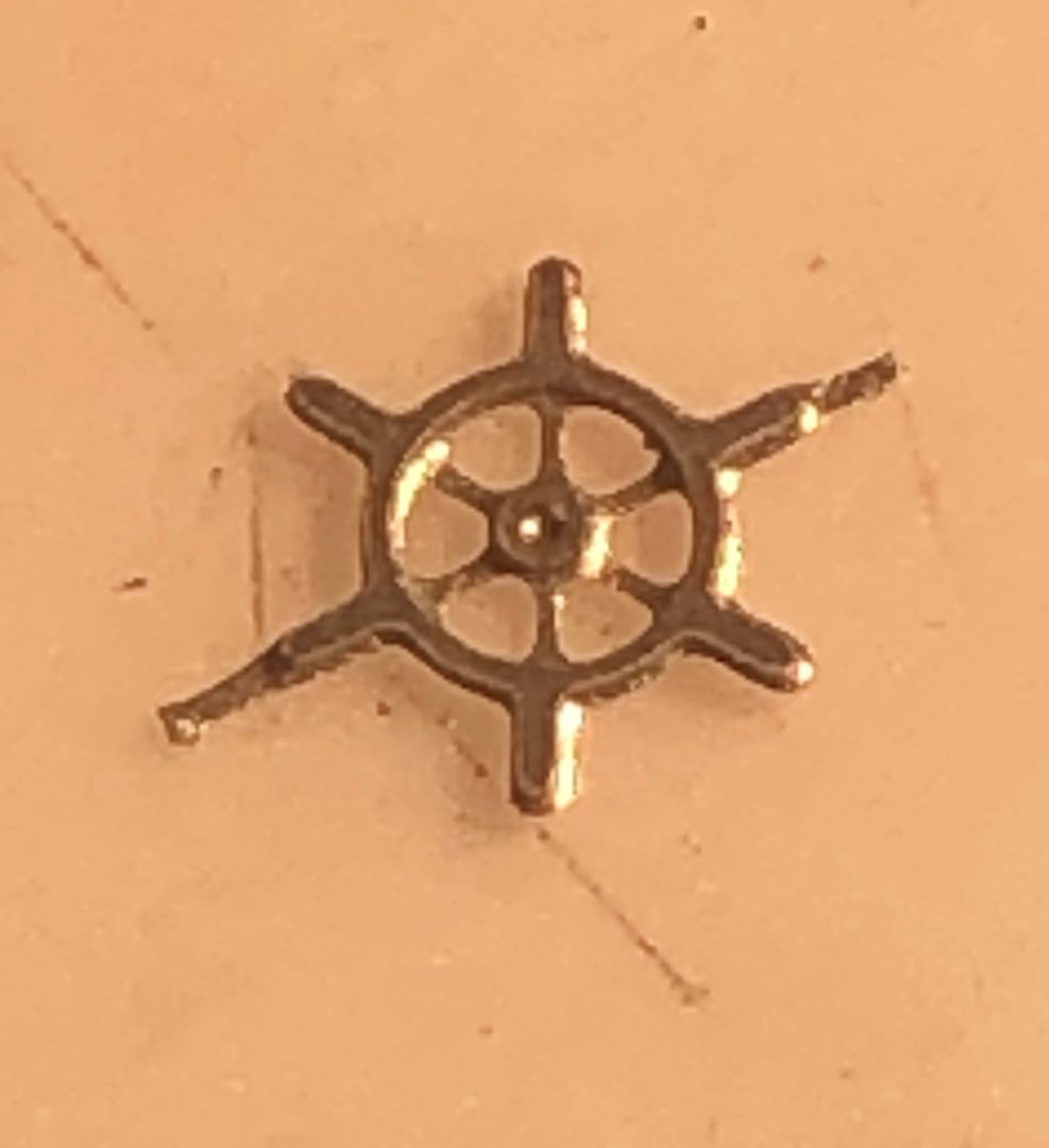
It’s a beautiful little etch, but there is no hole in the middle. Drilling this out free hand would have ended up with S shaped spokes or the carpet monster claiming another object, so I soldered it to a piece of brass to support it whilst drilling the 0.3 mm diameter hole.
In order to give it sufficient strength I think it needs the rod to go through the housing which was made from a piece of brass, again drilled 0.3mm and soldered on to the tender top.
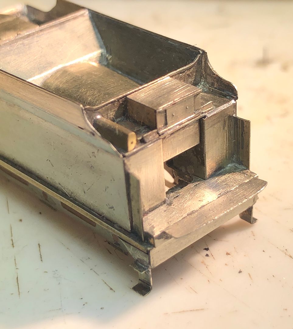
The wheel will be removable for the time being, whilst the engine and tender are being handled extensively during construction.
Tim

It’s a beautiful little etch, but there is no hole in the middle. Drilling this out free hand would have ended up with S shaped spokes or the carpet monster claiming another object, so I soldered it to a piece of brass to support it whilst drilling the 0.3 mm diameter hole.

In order to give it sufficient strength I think it needs the rod to go through the housing which was made from a piece of brass, again drilled 0.3mm and soldered on to the tender top.

The wheel will be removable for the time being, whilst the engine and tender are being handled extensively during construction.


Tim
-
Tim Watson
- GER D14 4-4-0 'Claud Hamilton'
- Posts: 310
- Joined: Mon Oct 24, 2016 11:37 am
Re: Copenhagen Fields & TFW’s workshop
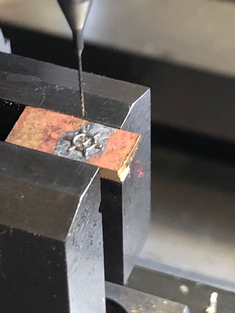
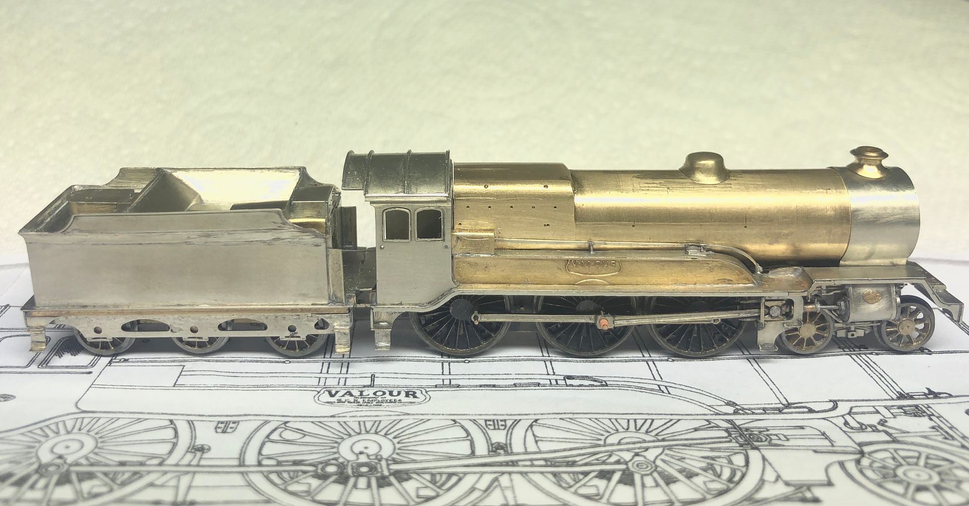
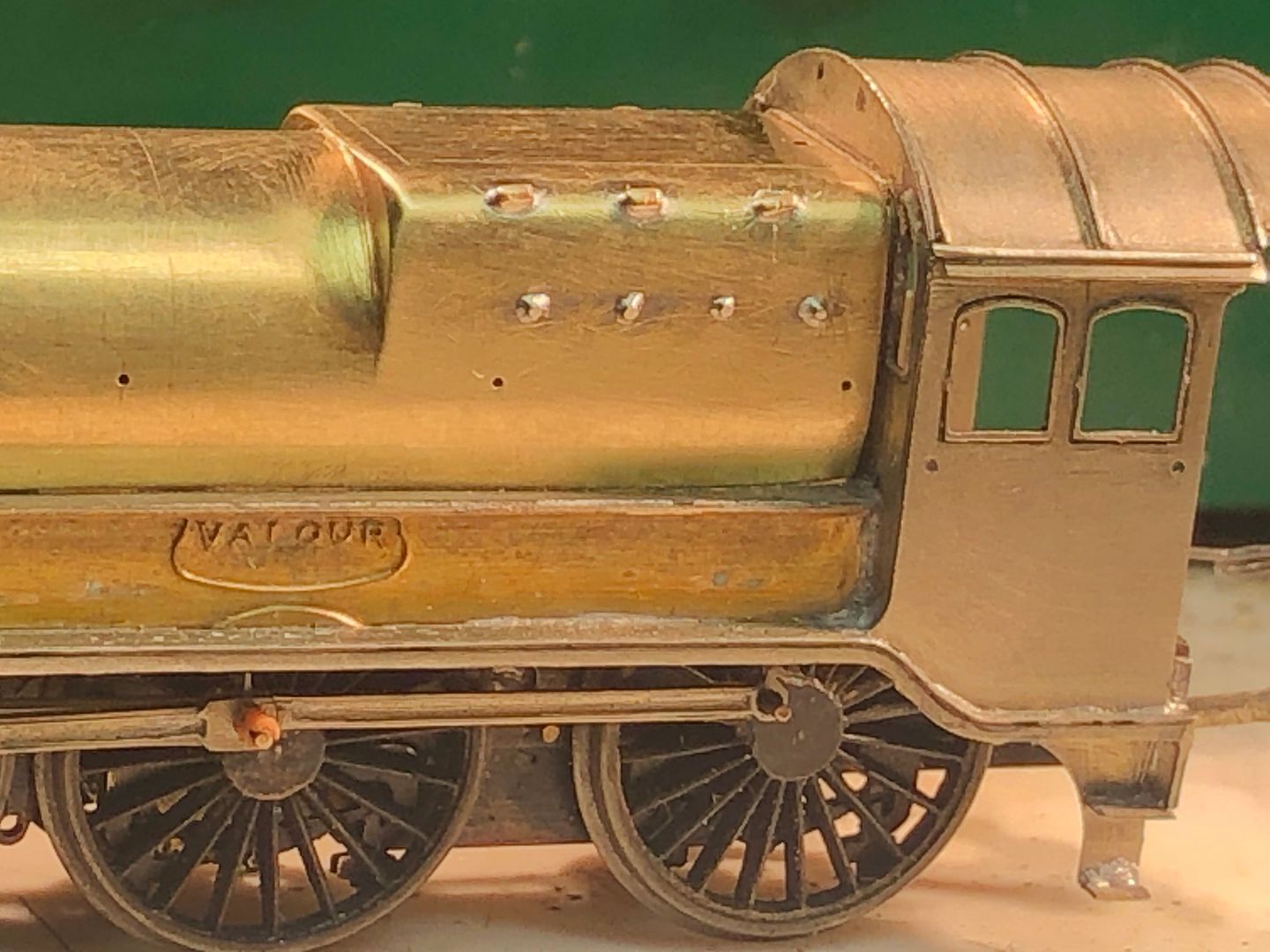
More progress on Valour, although maybe not immediately obvious from the previous overall shots. Steps on the engine & tender, water filler details on the tender and 22 x 0.3/0.5mm diameter holes in the boiler for washout plugs, handrail stanchions & mud hole doors.
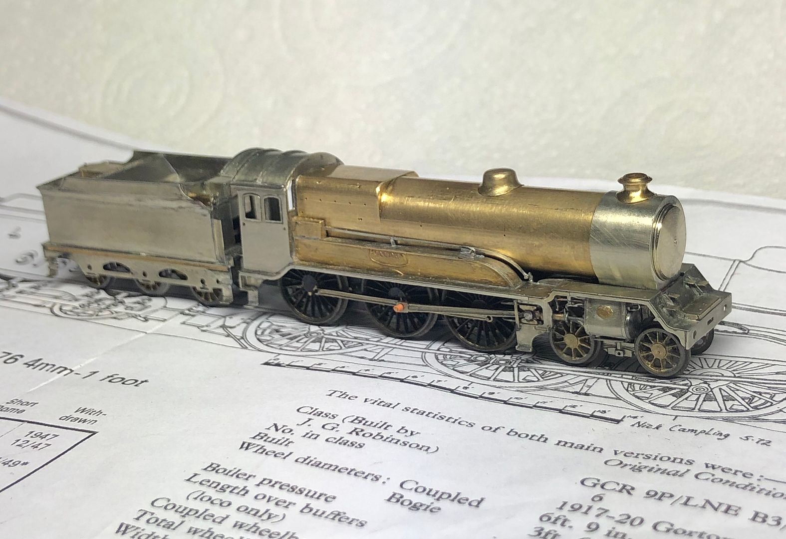
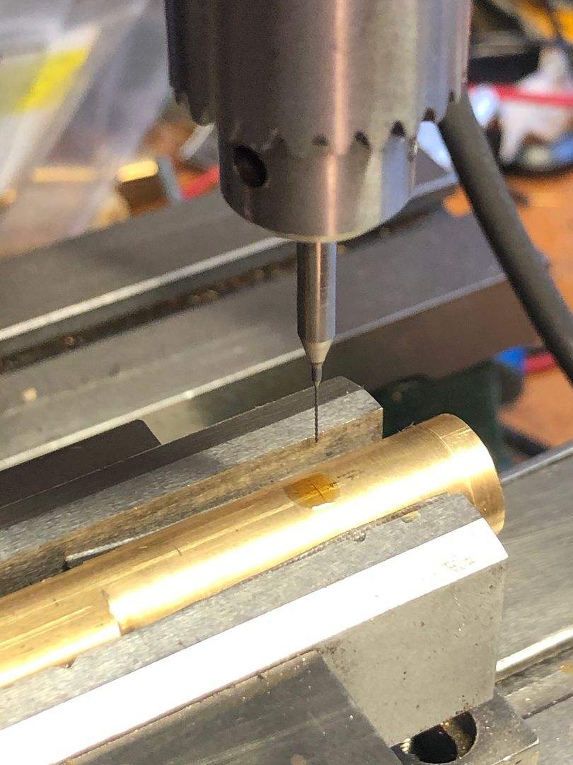
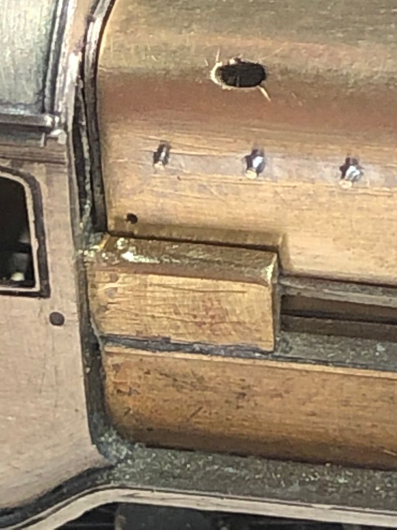
I had one drill ‘separate’ (as endodontists call it) - maybe you can spot where?
The boiler barrel was wrapped in some micro mesh abrasive cloth to hold it in the vice for drilling and avoid any marks from the jaws. The TC drills are very sharp but need coolant (Rocol RTD - visible over the cross mark).
The tender top is now soldered on, but with it tightly in place, I needed to make a bit more room for the brass stay alive, with some modification to the coal cover. Maybe buffers next.
Tim

I had one drill ‘separate’ (as endodontists call it) - maybe you can spot where?

The boiler barrel was wrapped in some micro mesh abrasive cloth to hold it in the vice for drilling and avoid any marks from the jaws. The TC drills are very sharp but need coolant (Rocol RTD - visible over the cross mark).

The tender top is now soldered on, but with it tightly in place, I needed to make a bit more room for the brass stay alive, with some modification to the coal cover. Maybe buffers next.
Tim
-
Atlantic 3279

- LNER A4 4-6-2 'Streak'
- Posts: 6534
- Joined: Fri Jun 26, 2009 9:51 am
- Location: 2850, 245
Re: Copenhagen Fields & TFW’s workshop
I must remember that I never "break" things, they just "separate"  .
.
Most subjects, models and techniques covered in this thread are now listed in various categories on page1
Dec. 2018: Almost all images that disappeared from my own thread following loss of free remote hosting are now restored.
Dec. 2018: Almost all images that disappeared from my own thread following loss of free remote hosting are now restored.
Re: Copenhagen Fields & TFW’s workshop
Such a shame that the self trimming tender isn't available in 4mm.
Re: Copenhagen Fields & TFW’s workshop
Just had an enjoyable 15 minutes catching up with latest progress, Tim. Fantastic work as always
Graham
Graham
(recreating pre-war Grantham in model form http://www.lner.info/forums/viewtopic.php?f=3&t=9076.
Forthcoming exhibition appearances: Newcastle (Nov 2023); York (Easter 2024); Bristol (May 2024)
Forthcoming exhibition appearances: Newcastle (Nov 2023); York (Easter 2024); Bristol (May 2024)
-
Tim Watson
- GER D14 4-4-0 'Claud Hamilton'
- Posts: 310
- Joined: Mon Oct 24, 2016 11:37 am
Re: Copenhagen Fields & TFW’s workshop
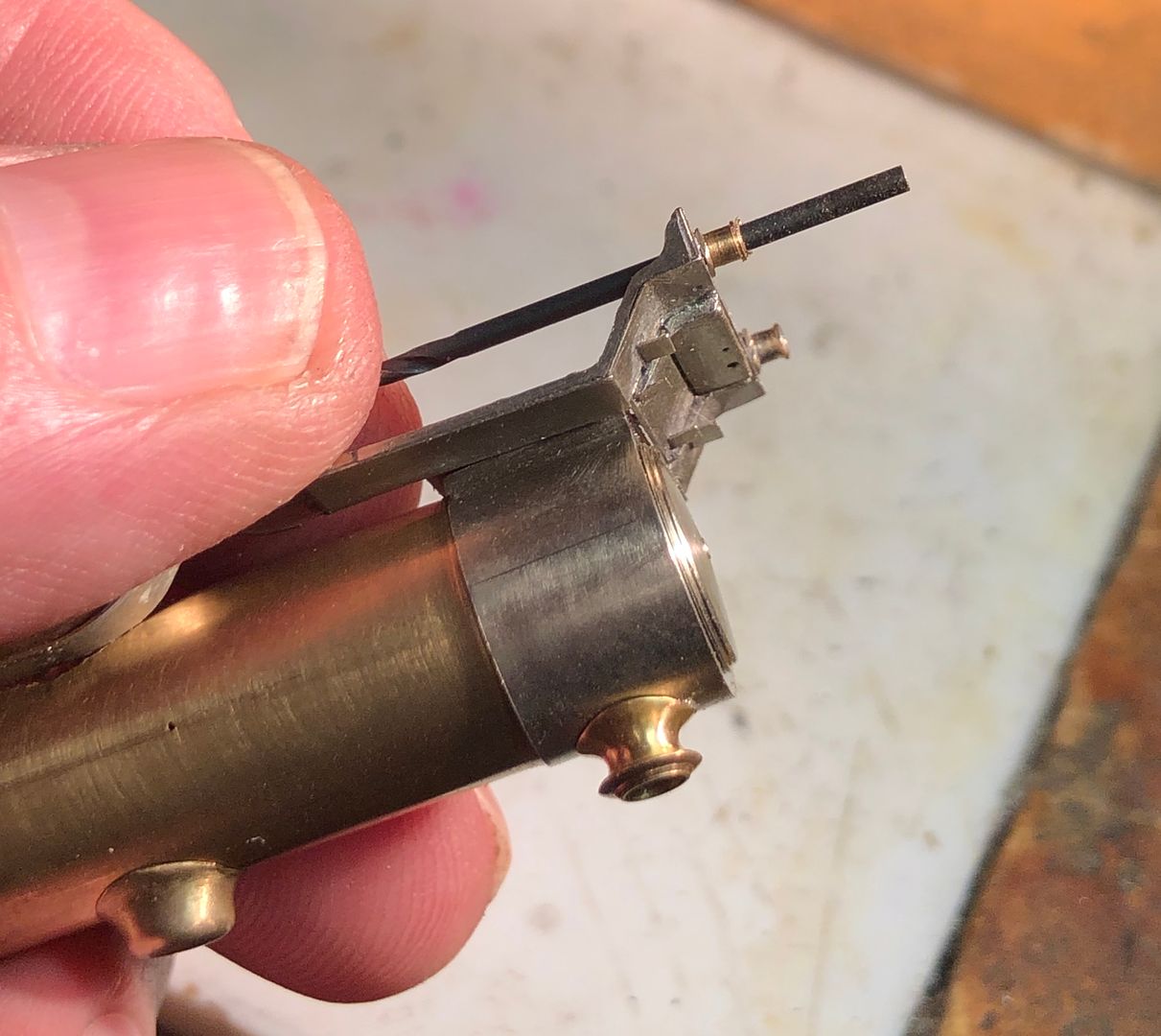
Valour now has the washout the plugs on one side of the firebox and some oval holes for the mud hole doors. I have also represented an inspection hatch on the reversing gear with a bit of filing.
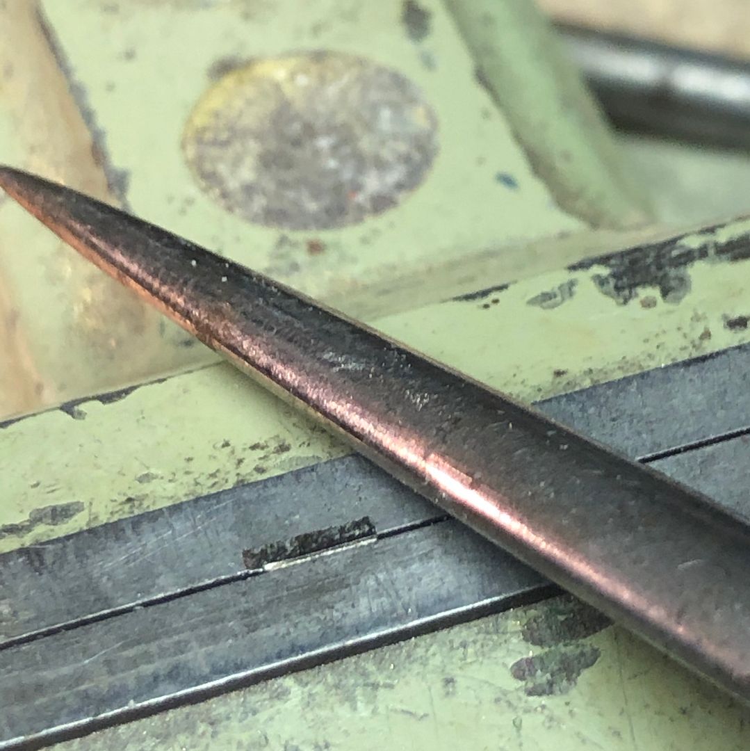
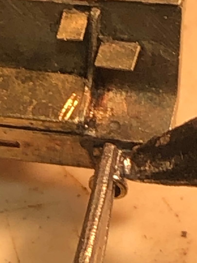
The front buffers were turned from some 15A plug brass (off an old Hornby Dublo controller that my son found). They were parted off with a slitting file and the drill shank reversed and ‘up the hole’. That way they do not fly off into outer space.
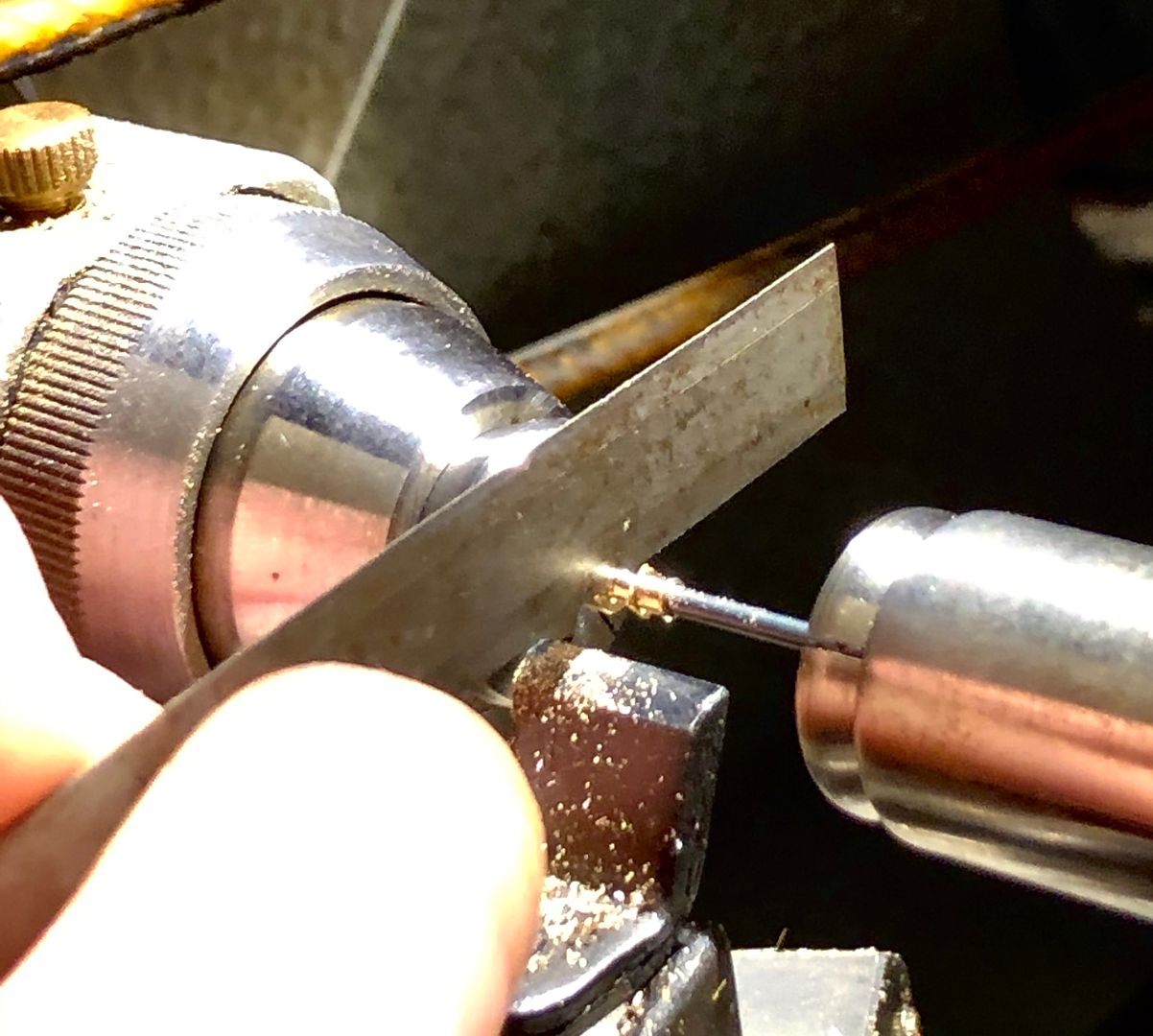
The same drill shank was used to help align the buffer stocks in the beam, whilst soldering into place. Drill shanks will not accept normal soft solder.
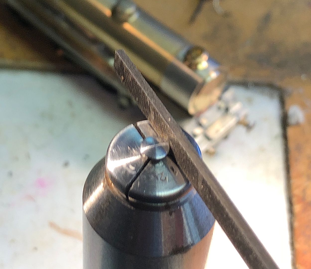
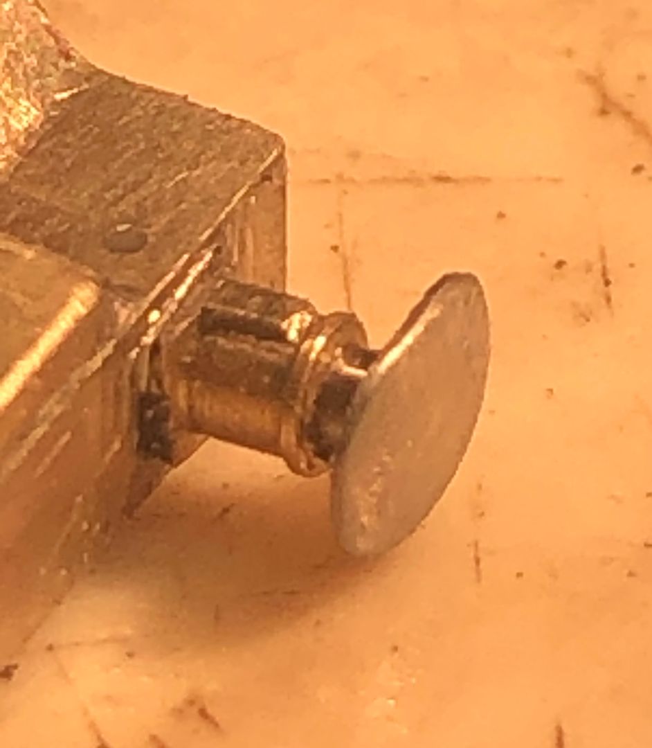
The buffers were turned, oversize, from steel and then filed top and bottom to make oval, using the slot in the collet as a guide (a pin chuck would also serve).
The over-thick top & bottom of the buffer heads were reduced by using abrasive points in the mini drill.
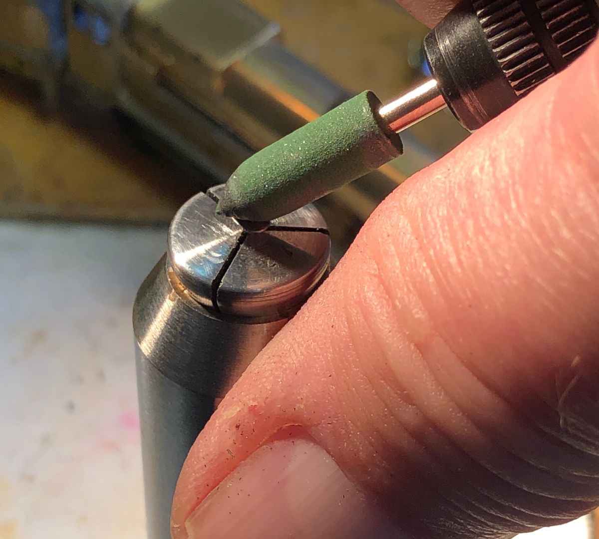
Finally finished off with some micro mesh polishing cloth.
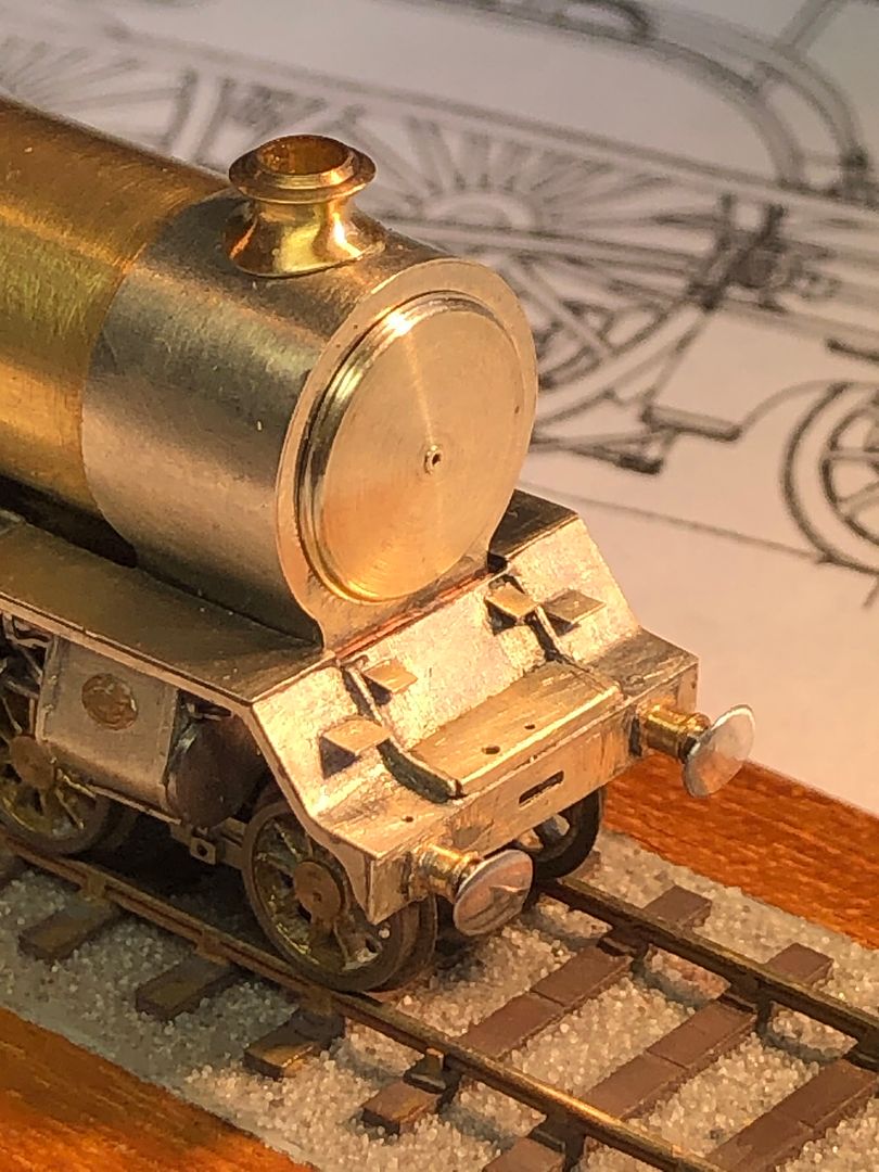
Tim

The front buffers were turned from some 15A plug brass (off an old Hornby Dublo controller that my son found). They were parted off with a slitting file and the drill shank reversed and ‘up the hole’. That way they do not fly off into outer space.

The same drill shank was used to help align the buffer stocks in the beam, whilst soldering into place. Drill shanks will not accept normal soft solder.

The buffers were turned, oversize, from steel and then filed top and bottom to make oval, using the slot in the collet as a guide (a pin chuck would also serve).

The over-thick top & bottom of the buffer heads were reduced by using abrasive points in the mini drill.

Finally finished off with some micro mesh polishing cloth.

Tim
-
Tim Watson
- GER D14 4-4-0 'Claud Hamilton'
- Posts: 310
- Joined: Mon Oct 24, 2016 11:37 am
Re: Copenhagen Fields & TFW’s workshop
There are little steps on the buffer stops which are quit conspicuous and give them a bit of mass. Putting the buffer steps on was easier than expected. The step and stock were tinned and then the two held together with titanium tweezers. Quick flash with iron
and hey presto!
The two small steps have subsequently been cured of droopiness btw.
Tim

and hey presto!

The two small steps have subsequently been cured of droopiness btw.
Tim
-
Tim Watson
- GER D14 4-4-0 'Claud Hamilton'
- Posts: 310
- Joined: Mon Oct 24, 2016 11:37 am
Re: Copenhagen Fields & TFW’s workshop
The mud hole doors have been made by chain drilling five oval holes with a 0.5mm diameter drill on the shoulders of the firebox.
The covers were made up from a squeezed bit of brass rod.
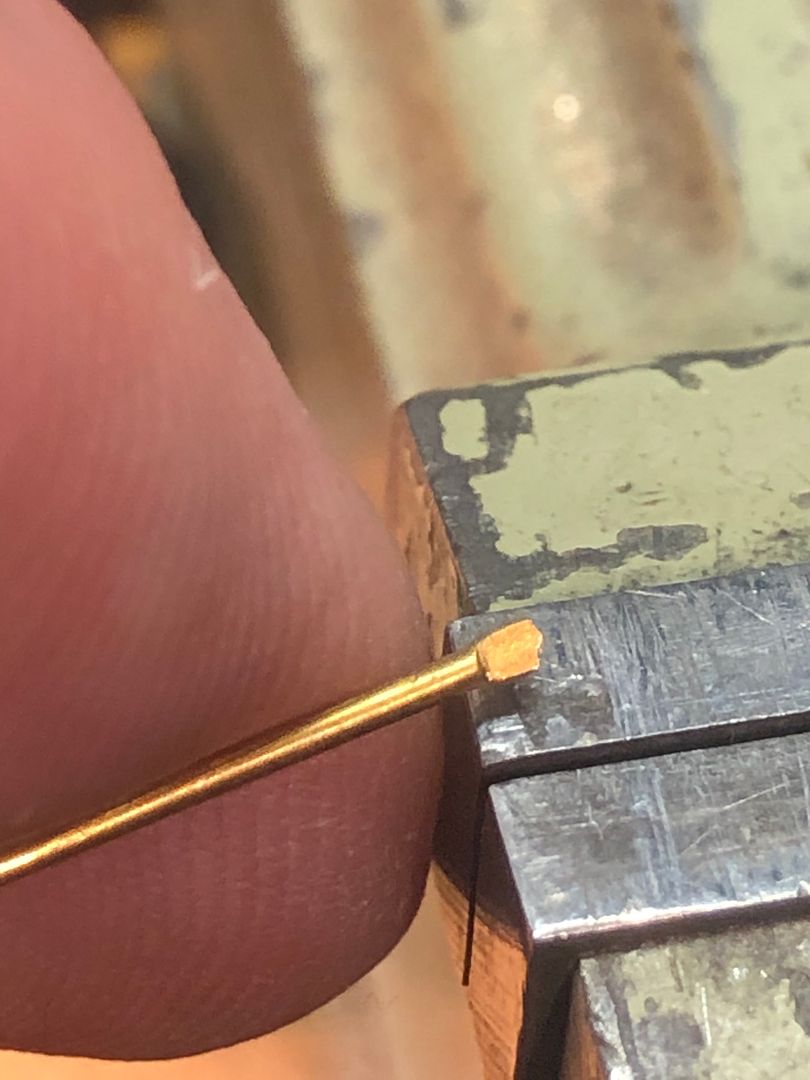
The cut off squeezed pieces were pushed into the holes and a small piece of multi core solder placed over the top of each.
The back of the firebox was slowly brought up to heat with a blow torch with a splash of acid flux to help the flow.
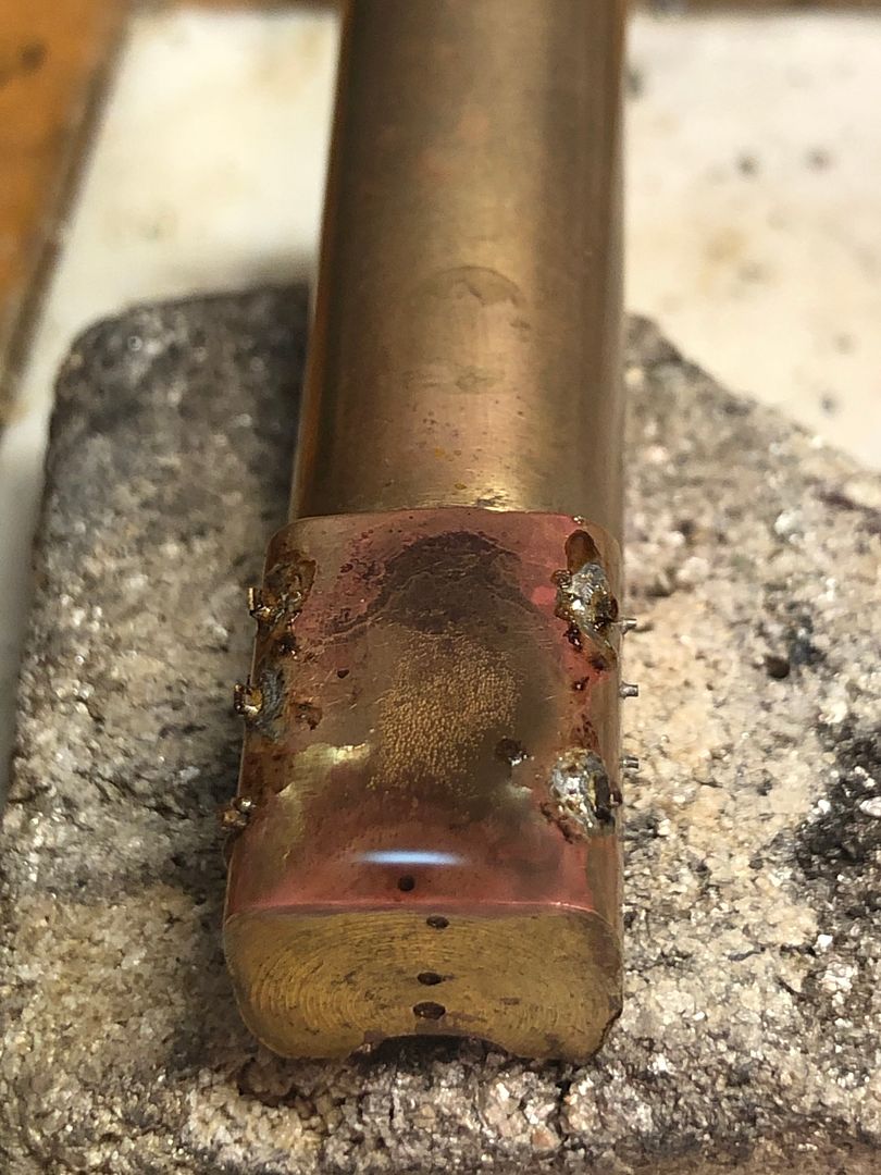
After knocking the corners off with a file and polishing, the mud hole doors finish off the firebox sides.
She’s looking awfully empty on top.
Tim

The covers were made up from a squeezed bit of brass rod.

The cut off squeezed pieces were pushed into the holes and a small piece of multi core solder placed over the top of each.

The back of the firebox was slowly brought up to heat with a blow torch with a splash of acid flux to help the flow.

After knocking the corners off with a file and polishing, the mud hole doors finish off the firebox sides.

She’s looking awfully empty on top.
Tim
-
drmditch
Re: Copenhagen Fields & TFW’s workshop
Continuing amazing modelling. Continuing amazement!
-
manna

- LNER A4 4-6-2 'Streak'
- Posts: 3793
- Joined: Sun May 24, 2009 12:56 am
- Location: All over Australia
Re: Copenhagen Fields & TFW’s workshop
G'Day Gents
Kinda makes a lot of peoples efforts look puny by comparison. I'm looking forward to how you fit the wicks inside the working headlamps.
manna
Kinda makes a lot of peoples efforts look puny by comparison. I'm looking forward to how you fit the wicks inside the working headlamps.
manna
EDGWARE GN, Steam in the Suburbs.
-
Tim Watson
- GER D14 4-4-0 'Claud Hamilton'
- Posts: 310
- Joined: Mon Oct 24, 2016 11:37 am
Re: Copenhagen Fields & TFW’s workshop
It’s been a bit of a slow job over the last couple of days making the hinge for the smokebox door. This was filed up from 10 thou steel sheet. It took three goes to get the shape right and the hinge pin correct.
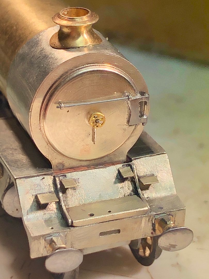
I have also roughed out the smokebox dart and wheel. This has a temporary LNWR five spoke wheel - it should be four spoke - from an etched brass Jumbo kit: it is clearly the wrong colour. Incidentally, anyone interested in the loco & tender kit, let me know as it is not an engine I will be making. A friend has kindly offered me a nickel silver wheel which should look better. However, I might have a go at making my own four spoke wheel in steel
Tim