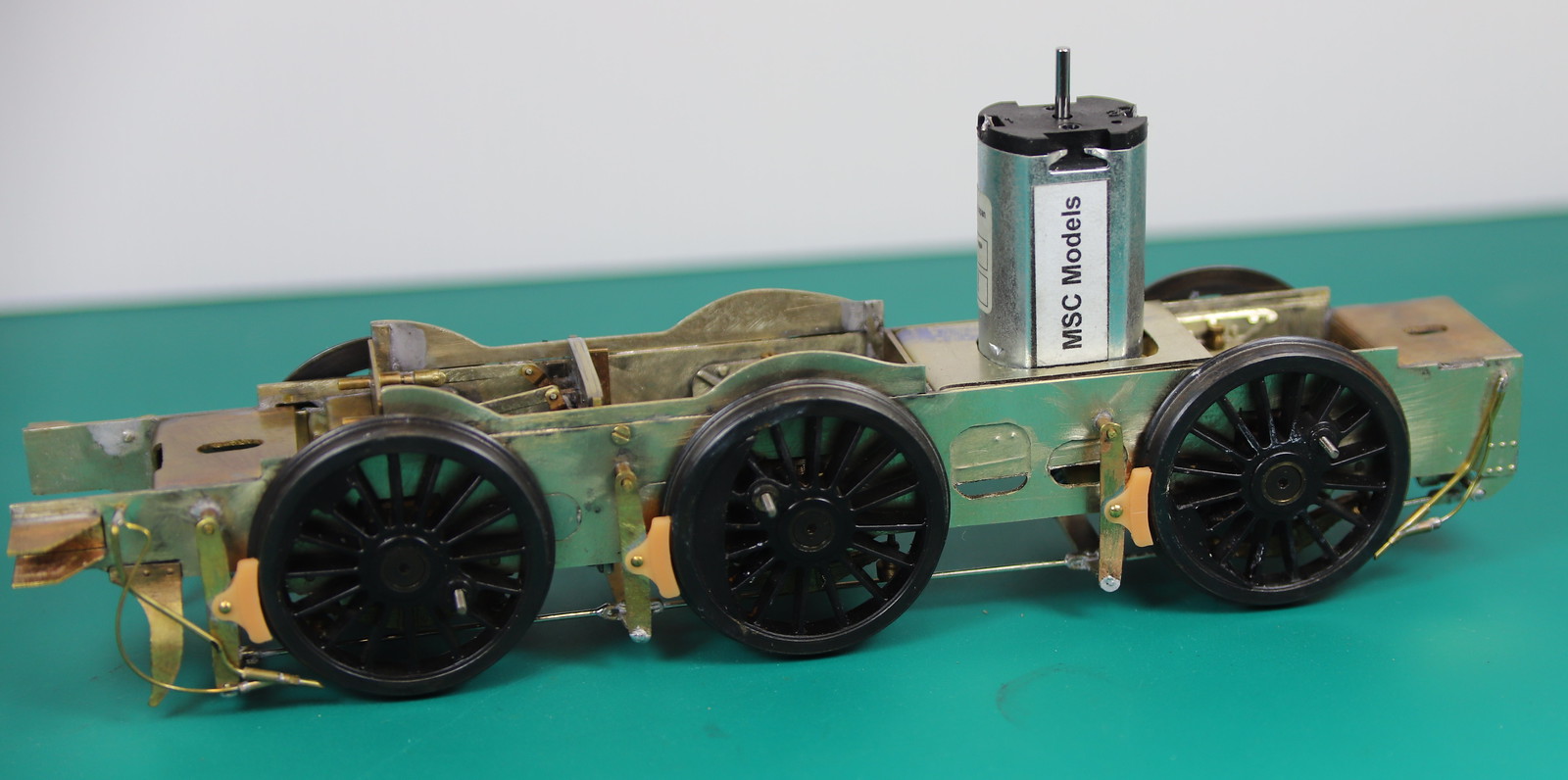
So much so that I plan to make up another chassis with inside motion for my demo stand.
On the back of a great weekend out I decided to see if I could crack the construction elements of the J6 last week.
The remaining jobs were.
Fit glazing
Add Milliput to the back of the balance weights to make them solid rather than just an etched front.
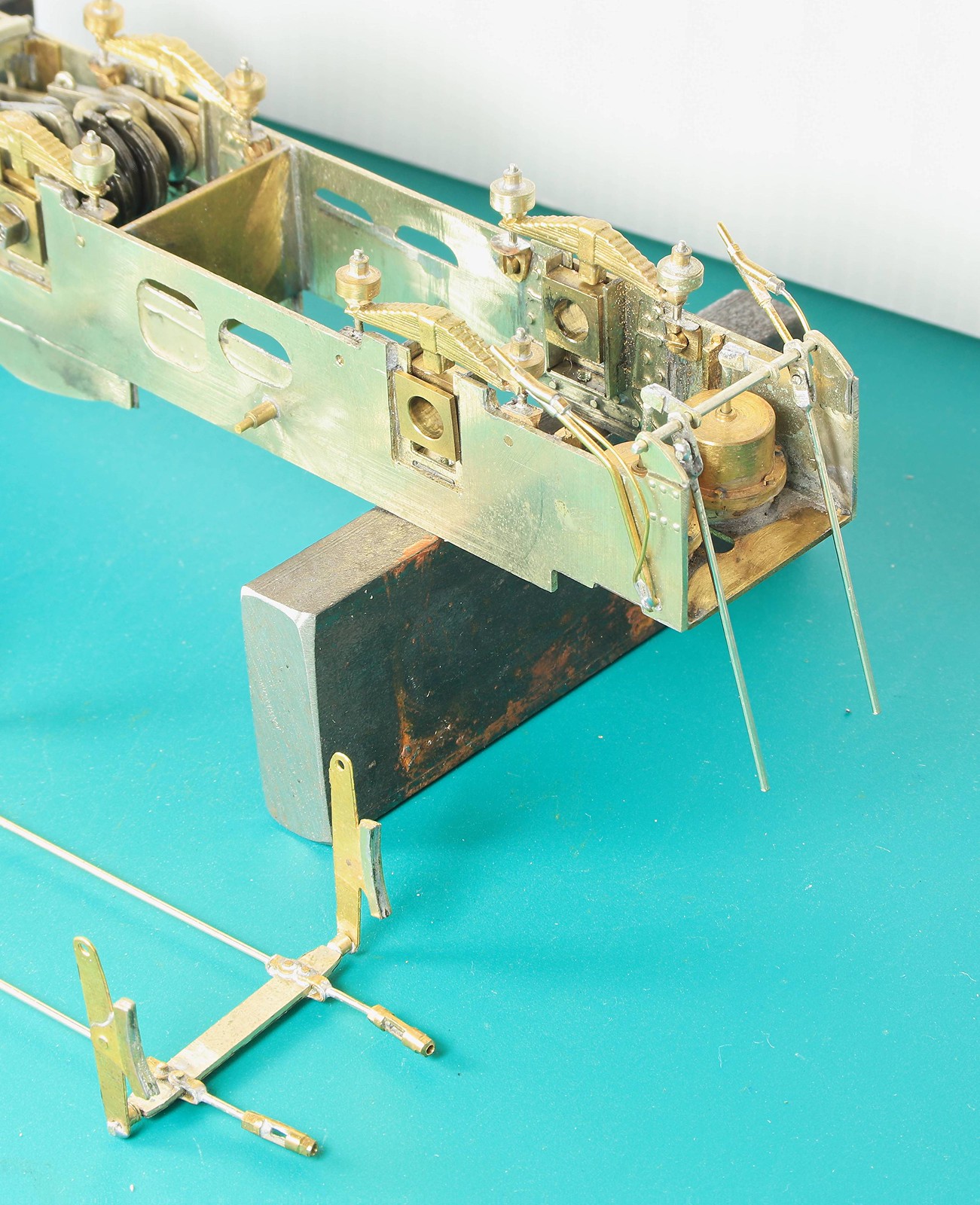
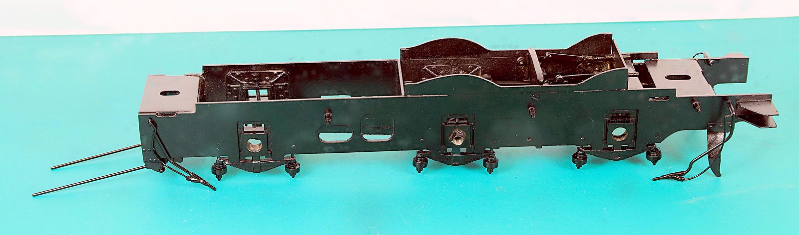
Fit the sand pipes
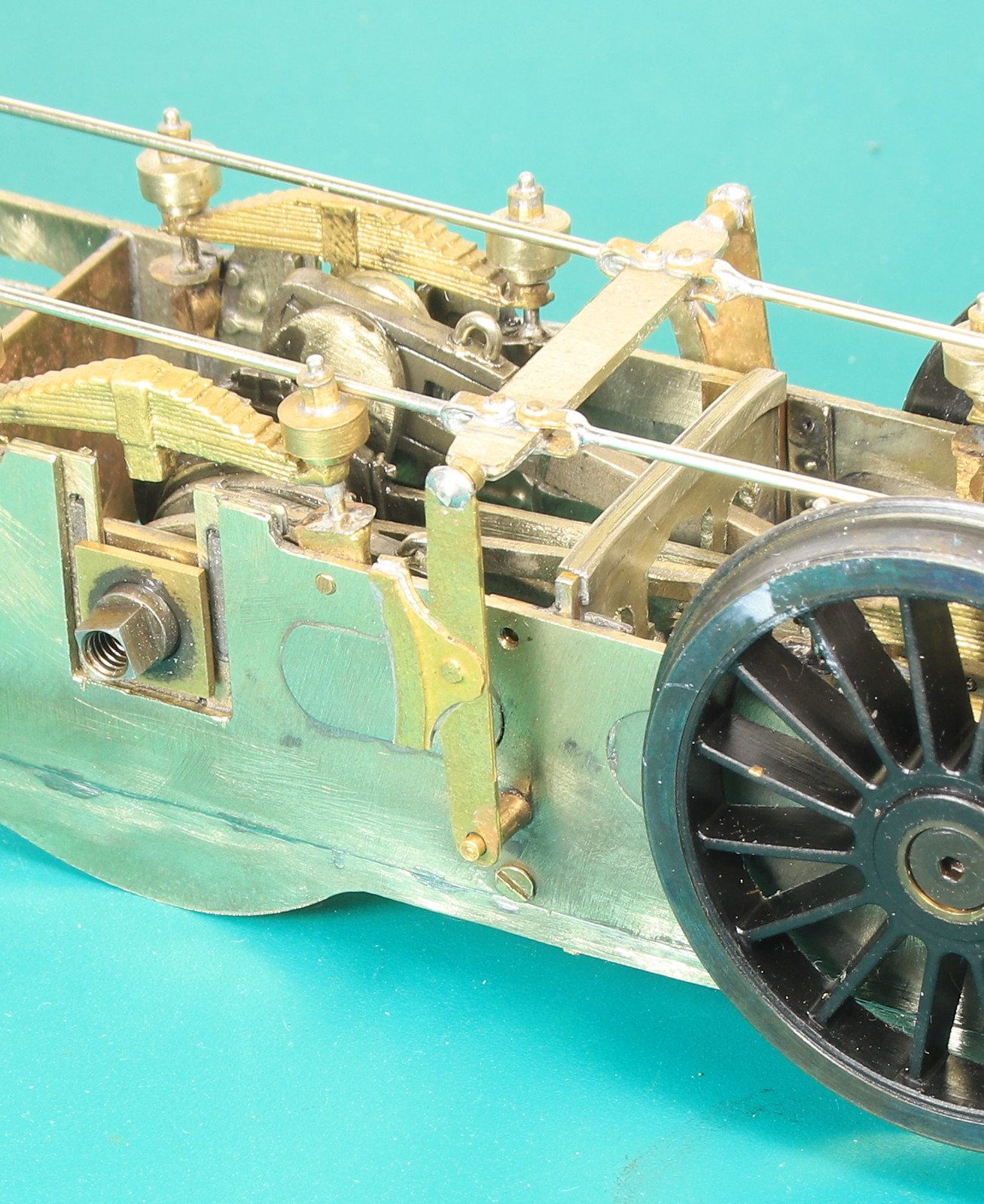
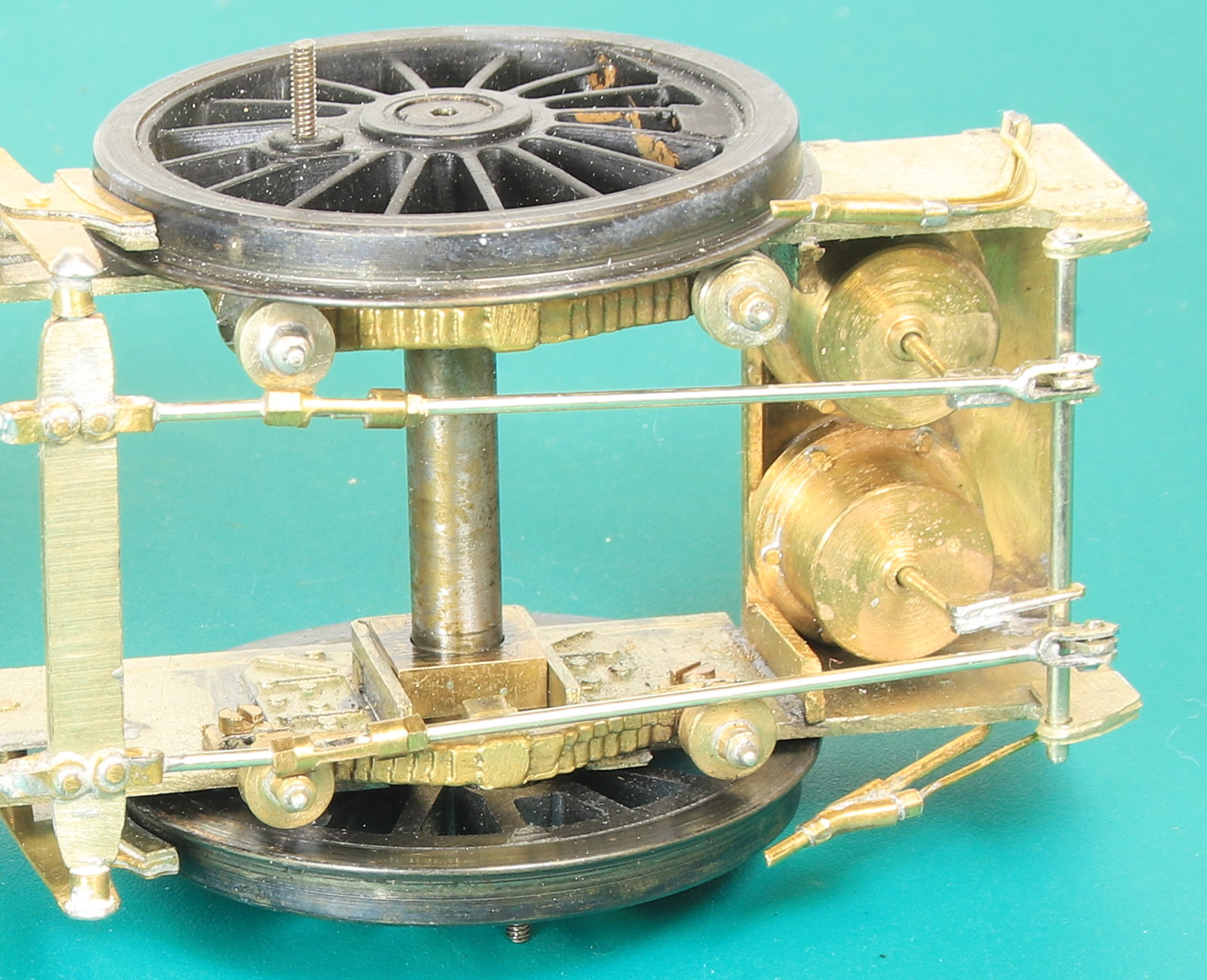
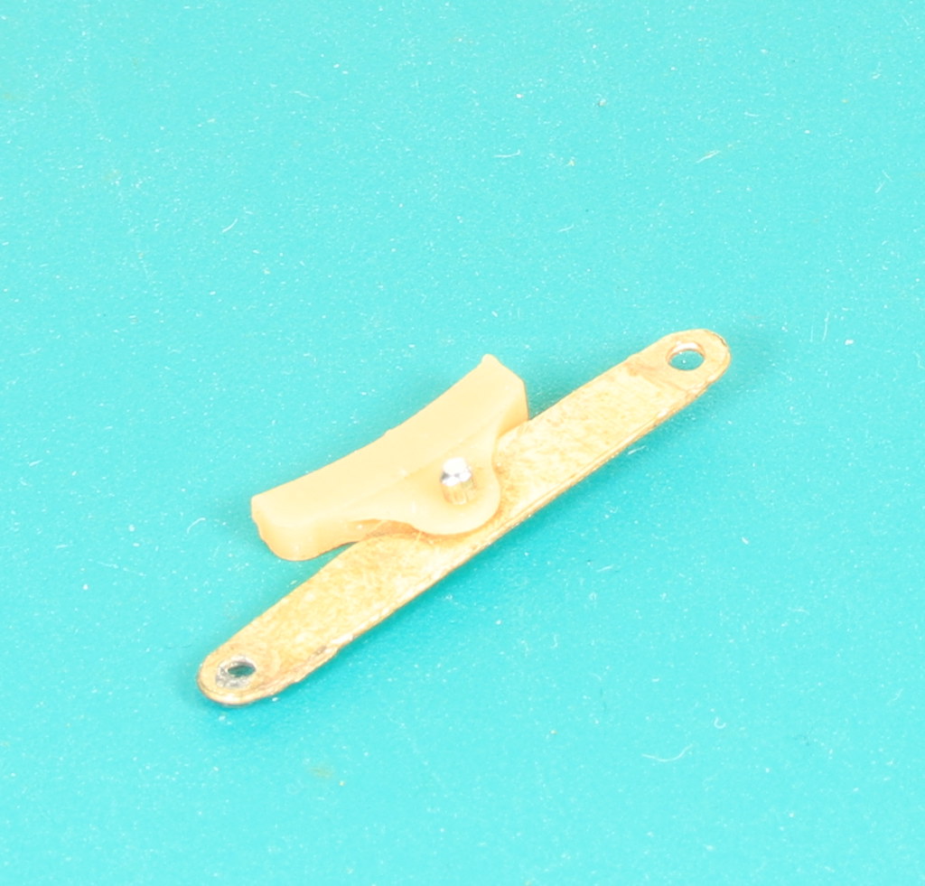
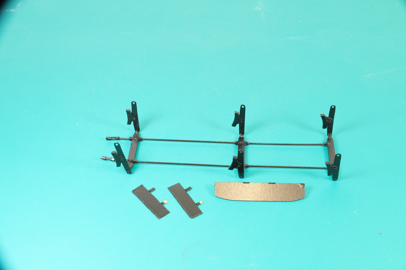
Fit the remaining linkages between the brake pull rods and the brake cylinders
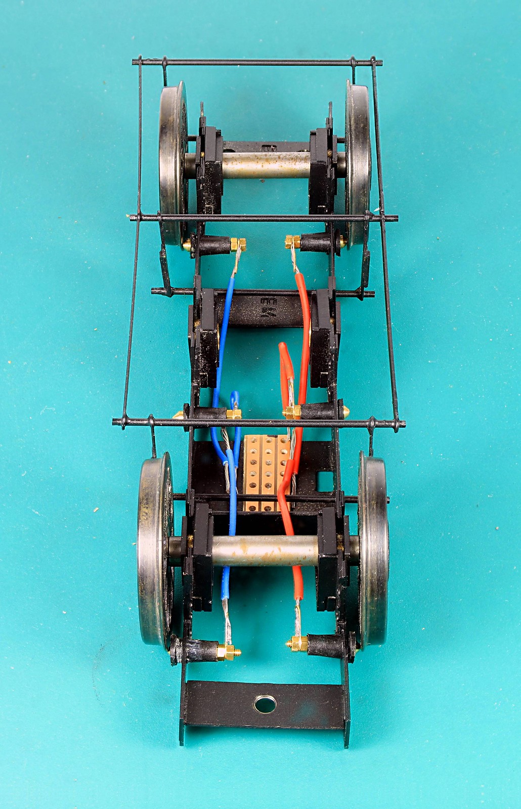
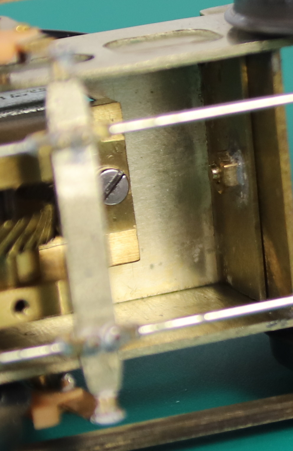
Fit some Frame extensions under the boiler between the front pairs of wheels to hide the rear of the wheels – following Tony Geary’s lead.

Balance weights, I added a coat of primer to bled it all in before final paint and weathering.
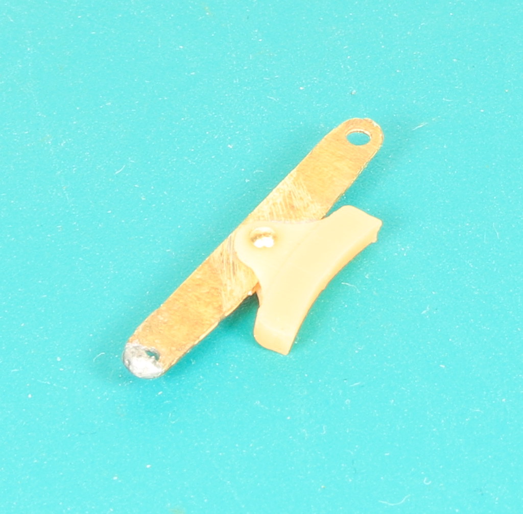
The first bit of the brake linkages

Front sandpipes and Frame extensions. Before fully soldering them in I tested the frame extensions at one side by tacking them in and the seemed perfect. But the chassis mustn’t have sat down properly because I noted while testing for clearance on the rear sandpipes that they need trimming down a bit.

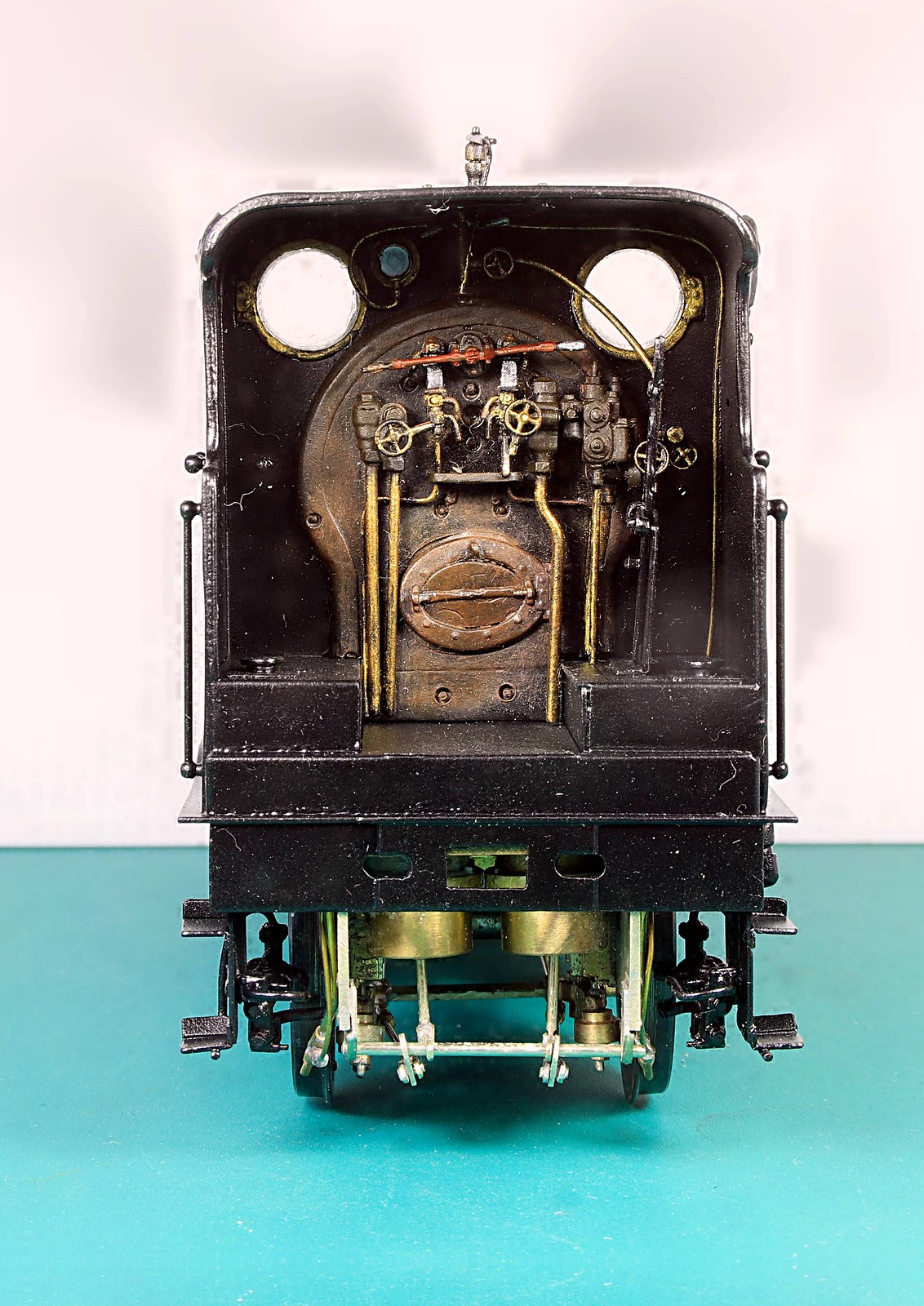
Rear sandpipes. I had to fit the tops of them very close to the frames to avoid the injector pipework but I got there after two or three adjustments.


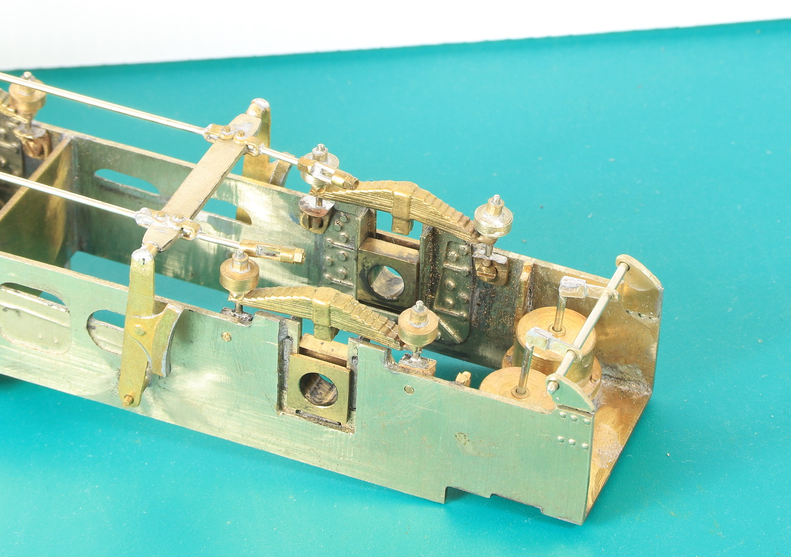
Last but not least a couple of shot of the remaining brake linkages. Although soldered at the rear the ends of the rods are a loose fit in the turnbuckles so allowing removal of the brakes.